Verilog数字钟设计(开发板实际验证,含演示视频)
2019-07-28 18:55
204 查看
版权声明:本文为博主原创文章,遵循 CC 4.0 by-sa 版权协议,转载请附上原文出处链接和本声明。
本文链接:https://blog.csdn.net/qq_42181309/article/details/90175698
- 本博客的数字钟采用的是开关方法,若想了解按钮方法,可阅读完这篇博客,转向我的另一篇博客https://blog.csdn.net/qq_42181309/article/details/90637339
- 数字钟网上有很多的方法,写的呢仅供参考。主要是分享一下思路。验证是在xilinx vivado套件选择xc7a100tcsg324-1的开发板下验证的。就是学生实验教学用的开发板。
- 首先是功能构想,数字钟应该有什么功能。整体功能:数码管一共是8个的对吧,要用到其中6个。分别显示时分秒位。然后有个校时功能。那再细分一下,要实现这个整体功能,需要什么呢。
- 首先要有俩分频模块,第一个分频用于计时,即每秒进位,然后带动分位,带动小时位,你也可以说它是计时模块。另外一个分频模块,因为多个数码管显示运用的视觉停留的原理,所以要分频用于数码管的显示。
- 其次就是译码模块,为什么要译码?因为计时的时候,你用简单的加法,方便计数。但显示的时候,比如数字7,你需要的是一个8位宽的序列。所以我们要译码。这里有一个考量,用六个译码器还是一个译码器?六个译码器,即对时分秒位,每个位两个数字,如13:59:59,同时译码。一个译码器就是在分频显示的时候再译码,比如你要显示13:59:59里的5的时候再对5的位置译码,即先决定显示哪位再译码。这个方法很省资源。但初学者的我,没控制好时许。所以最后只好采用6个译码器。
- 还有三注意事项,就是非法值检验和小数点了。13:59:57。需要在3和9位显示小数点。这也是我采用6个译码器的原因。你只要在分频显示的时候显示到3或者9的时候,改下小数点。还有非法检验,比如你要校准为25:59:59,这铁定是不能让你输入的。这加点预处理就行。
- 最后一个注意事项是划分模块一定要细,如果采用行为级描述,心里要有个底,最好写tb文件验证,因为ADT工具不是很好,想像C语言那样你可就大错特错了。
- 到这基本原理就结束了,下面是具体实现。
-
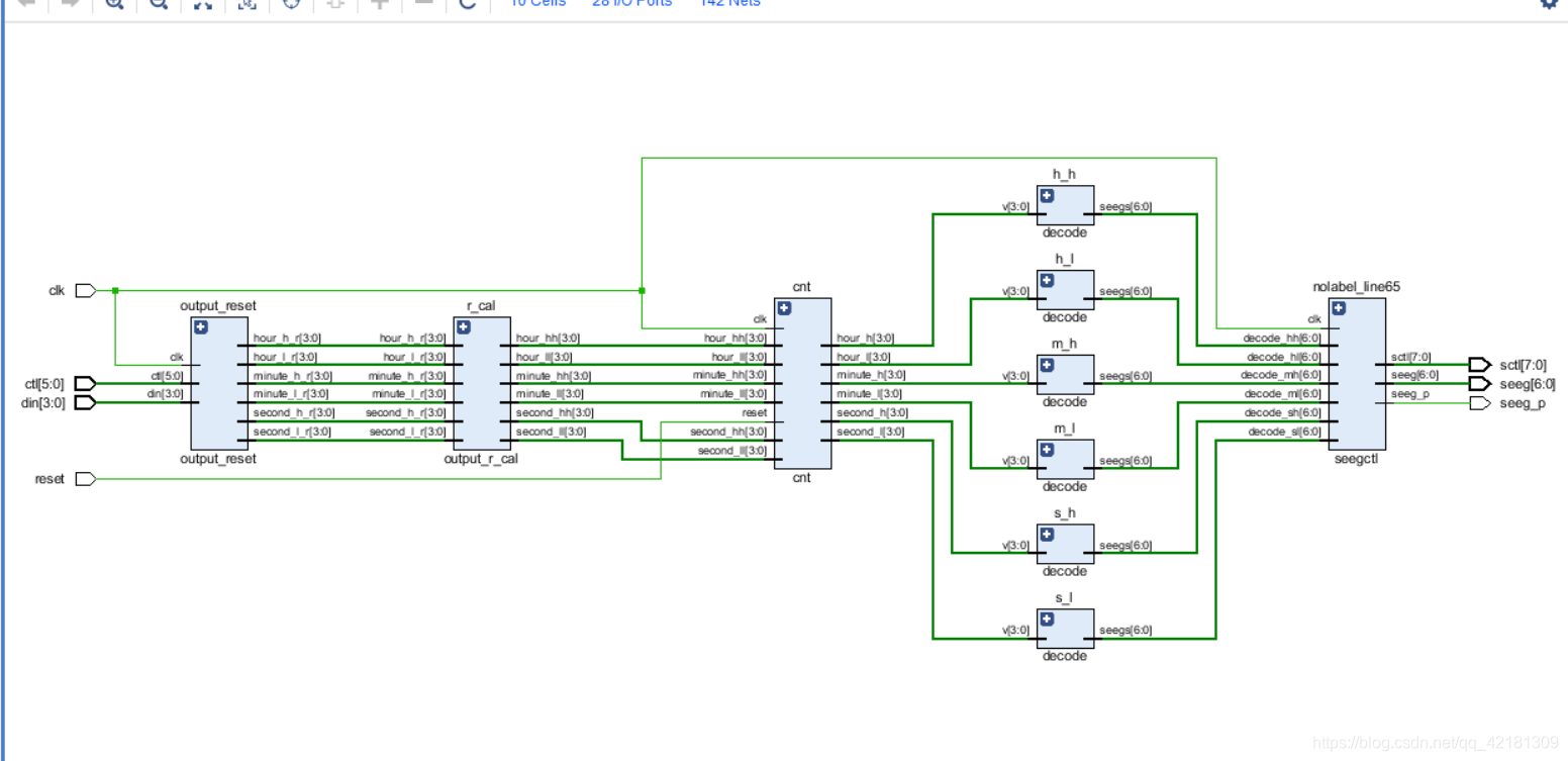
- 这是我的实现方式,需要用IO口有11个,4个din用于确保数字0到9(BCD),6位ctl用来决定你是要矫正哪位,其它5位就保持不动,所以这是个时许电路,时钟上升沿加载。第一个outputreset模块,输出校准后的时分秒,r_cal模块是二次矫正,为什么要二次矫正比如你矫正完位27:11:12,二次矫正后就为23:11:12,即非法检验。
- 接着就到了cnt计时模块,我将reset信号用于加载信号,如果reset就加载矫正后的值,当reset为0时,从当前值开始计数。
- cnt模块连着6个译码器decode模块,即同时译码。之后seegctl通过分频来分别显示时分秒位。注意译码器是7位的,即我们没决定小数点是否显示,而是在seegctl决定的,其实译码那里决定也可以。都行,仅供参考。
- 下面是参考源代码
- .top,主要用于模块的连接
[code]module top(
input clk,
input reset,
input [3:0] din,
input [5:0]ctl,
output [6:0] seeg,
output [7:0] sctl,
output seeg_p
);
wire [6:0]decode_hh;
wire [6:0]decode_hl;
wire [6:0]decode_mh;
wire [6:0]decode_ml;
wire [6:0]decode_sh;
wire [6:0]decode_sl;
wire [3:0] second_l;
wire [3:0] second_h;
wire [3:0]minute_l;
wire [3:0]minute_h;
wire [3:0]hour_l;
wire [3:0]hour_h;
wire [3:0] second_l_r;
wire [3:0] second_h_r;
wire [3:0]minute_l_r;
wire [3:0]minute_h_r;
wire [3:0]hour_l_r;
wire [3:0]hour_h_r;
wire [3:0] second_ll;
wire [3:0] second_hh;
wire [3:0]minute_ll;
wire [3:0]minute_hh;
wire [3:0]hour_ll;
wire [3:0]hour_hh;
output_reset output_reset(.clk(clk),.din(din),.ctl(ctl),.second_l_r(second_l_r),.second_h_r(second_h_r),.minute_l_r(minute_l_r),.minute_h_r(minute_h_r),.hour_l_r(hour_l_r),.hour_h_r(hour_h_r));
output_r_cal r_cal(.second_l_r(second_l_r),.second_h_r(second_h_r),.minute_l_r(minute_l_r),.minute_h_r(minute_h_r),.hour_l_r(hour_l_r),.hour_h_r(hour_h_r),.second_ll(second_ll),.second_hh(second_hh),.minute_ll(minute_ll),.minute_hh(minute_hh),.hour_ll(hour_ll),.hour_hh(hour_hh));
cnt cnt(.reset(reset),.clk(clk),.second_ll(second_ll),.second_hh(second_hh),.minute_ll(minute_ll),.minute_hh(minute_hh),.hour_ll(hour_ll),.hour_hh(hour_hh),.hour_h(hour_h),.hour_l(hour_l),.minute_h(minute_h),.minute_l(minute_l),.second_h(second_h),.second_l(second_l));
decode h_h(.v(hour_h),.seegs(decode_hh));
decode h_l(.v(hour_l),.seegs(decode_hl));
decode m_h(.v(minute_h),.seegs(decode_mh));
decode m_l(.v(minute_l),.seegs(decode_ml));
decode s_h(.v(second_h),.seegs(decode_sh));
decode s_l(.v(second_l),.seegs(decode_sl));
seegctl(.decode_hh(decode_hh),.decode_hl(decode_hl),.decode_mh(decode_mh),.decode_ml(decode_ml),.decode_sh(decode_sh),.decode_sl(decode_sl),.clk(clk),.seeg(seeg),.sctl(sctl),.seeg_p(seeg_p));
endmodule
output_reset,我在这里让输入校正只能为0到9,
[code]module output_reset(
input clk,
input [3:0] din,
input [5:0]ctl,
output reg [3:0] second_l_r,
output reg [3:0] second_h_r,
output reg [3:0]minute_l_r,
output reg [3:0]minute_h_r,
output reg [3:0]hour_l_r,
output reg [3:0]hour_h_r
);
reg[5:0] ctl_one;
reg[5:0] ctl_two;
reg [3:0]q;
reg[3:0]q1;
reg[3:0]q2;
always @*
if(din<10)
q=din;
else
q=din-8;
always @(posedge clk)
begin
ctl_one<=ctl;
ctl_two<=ctl_one;
q1<=q;
q2<=q1;
end
always @(posedge clk)
if(ctl_two[5]==1'b1)
hour_h_r<=q2;
else if(ctl_two[4]==1'b1)
hour_l_r<=q2;
else if(ctl_two[3]==1'b1)
minute_h_r<=q2;
else if(ctl_two[2]==1'b1)
minute_l_r<=q2;
else if(ctl_two[1]==1'b1)
second_h_r<=q2;
else if(ctl_two[0]==1'b1)
second_l_r<=q2;
endmodule
[code]module output_r_cal(
input [3:0] second_l_r,
input [3:0] second_h_r,
input [3:0]minute_l_r,
input [3:0]minute_h_r,
input [3:0]hour_l_r,
input [3:0]hour_h_r,
output [3:0] second_ll,
output [3:0] second_hh,
output [3:0]minute_ll,
output [3:0]minute_hh,
output [3:0]hour_ll,
output [3:0]hour_hh
);
assign hour_hh=(hour_h_r>2)? {3'b00,hour_h_r[0]}:hour_h_r;
assign hour_ll=(hour_h_r==2)? {2'b00,hour_l_r[1:0]}:hour_l_r;
assign minute_hh=(minute_h_r>5) ? {2'b0,minute_h_r[1:0]}:minute_h_r;
assign minute_ll=minute_l_r;
assign second_hh=(second_h_r>5) ? {2'b0,second_h_r[1:0]}:second_h_r;
assign second_ll=second_l_r;
endmodule
cnt,分频频率根据你板子的时钟频率来设置,我用的板子是100Whz的,所以我分频基数就为10**8。
[code]module cnt(
input clk,
input reset,
input  [3:0] second_ll,
input  [3:0] second_hh,
input  [3:0]minute_ll,
input  [3:0]minute_hh,
input  [3:0]hour_ll,
input  [3:0]hour_hh,
output reg [3:0] second_l,
output reg [3:0] second_h,
output reg [3:0]minute_l,
output reg [3:0]minute_h,
output reg [3:0]hour_l,
output reg [3:0]hour_h
);
parameter ST_N=30;//秒表分频频率N
reg [ST_N-1:0] wa_clk;//秒表分频时钟
reg reset_one;
reg reset_two;
reg  [3:0] second1_ll;
reg  [3:0] second1_hh;
reg  [3:0]minute1_ll;
reg  [3:0]minute1_hh;
reg  [3:0]hour1_ll;
reg  [3:0]hour1_hh;
reg  [3:0] second2_ll;
reg  [3:0] second2_hh;
reg  [3:0]minute2_ll;
reg  [3:0]minute2_hh;
reg  [3:0]hour2_ll;
reg  [3:0]hour2_hh;
always @(posedge clk)
begin
second1_ll<=second_ll;
second2_ll<=second1_ll;
second1_hh<=second_hh;
second2_hh<=second1_hh;
minute1_ll<=minute_ll;
minute2_ll<=minute1_ll;
minute1_hh<=minute_hh;
minute2_hh<=minute1_hh;
hour1_ll<=hour_ll;
hour2_ll<=hour1_ll;
hour1_hh<=hour_hh;
hour2_hh<=hour1_hh;
reset_one<=reset;
reset_two<=reset_one;
end
always @(posedge clk)//计时
if(reset_two)
begin
hour_h<=hour2_hh;
hour_l<=hour2_ll;
minute_h<=minute2_hh;
minute_l<=minute2_ll;
second_h<=second2_hh;
second_l<=second2_ll;
wa_clk<=0;
end
else
if(wa_clk<(10**8))
wa_clk<=wa_clk+1;
else
begin
wa_clk<={ST_N-1'b0,1'b1};//时钟复位
begin
if(second_l<9)
second_l<=second_l+1;
else
begin
second_l<=0;//复位
if(second_h<5)
second_h<=second_h+1;
else
begin
second_h<=0;
if(minute_l<9)
minute_l<=minute_l+1;
else
begin
minute_l<=0;//复位
if(minute_h<5)
minute_h<=minute_h+1;
else
begin
minute_h<=0;//复位

if((hour_h<2)&&(hour_l<9))
hour_l<=hour_l+1;
else if((hour_h==4'b0010)&&(hour_l<3))
hour_l<=hour_l+1;
else if((hour_h==4'b0010)&&(hour_l==3))//过了一天重新开始
begin
hour_l<=0;
hour_h<=0;
minute_l<=0;
minute_h<=0;
second_l<=0;
second_h<=0;
end
else
begin
hour_l<=0;//复位
hour_h<=hour_h+1;
end
end
end
end
end
end
end
endmodule
译码器
[code]module decode(
input [3:0] v,
output reg [6:0] seegs
);
always @*
begin
if(v==4'h0)
seegs=7'b1000000;
else if(v==4'h1)
seegs=7'b1111001;
else if(v==4'h2)
seegs=7'b0100100;
else if(v==4'h3)
seegs=7'b0110000;
else if(v==4'h4)
seegs=7'b0011001;
else if(v==4'h5)
seegs=7'b0010010;
else if(v==4'h6)
seegs=7'b0000010;
else if(v==4'h7)
seegs=7'b1111000;
else if(v==4'h8)
seegs=7'b0000000;
else
seegs=7'b0010000;
end
endmodule
seegctl,主要用于控制数码管的显示,由sctl,seeg和seep_p16位共同控制
[code]module seegctl(
input clk,
input wire [6:0]decode_hh,
input wire [6:0]decode_hl,
input wire [6:0]decode_mh,
input wire [6:0]decode_ml,
input wire [6:0]decode_sh,
input wire [6:0]decode_sl,
output reg [7:0]sctl,
output reg [6:0]seeg,
output reg seeg_p
);
parameter SEEG_N=19;//数码管分频频率N
reg [SEEG_N-1:0] seeg_clk;//数码管分频时钟
initial
begin
end
always @(posedge clk)//数码管分频,一共需要7个数码管所以分三位,sctl0位对应数码管亮的位置
begin
seeg_clk<=seeg_clk+1;
if(seeg_clk[SEEG_N-1:SEEG_N-3]==3'b111)
seeg_clk<=0;
end
always@*
if(seeg_clk[SEEG_N-1:SEEG_N-3]==3'b010)
begin
sctl=8'b11111110;
seeg=decode_sl;
seeg_p=1;
end
else if(seeg_clk[SEEG_N-1:SEEG_N-3]==3'b011)
begin
sctl=8'b11111101;
seeg=decode_sh;
seeg_p=1;
end
else if(seeg_clk[SEEG_N-1:SEEG_N-3]==3'b100)
begin
sctl=8'b11111011;
seeg=decode_ml;
seeg_p<=0;
end
else if(seeg_clk[SEEG_N-1:SEEG_N-3]==3'b101)
begin
sctl=8'b11110111;
seeg=decode_mh;
seeg_p=1;
end
else if(seeg_clk[SEEG_N-1:SEEG_N-3]==3'b110)
begin
sctl=8'b11101111;
seeg=decode_hl;
seeg_p=0;
end
else
begin
sctl=8'b11011111;
seeg<=decode_hh;
seeg_p<=1;
end
endmodule
运行效果,由于没有不能上传视频只能附图
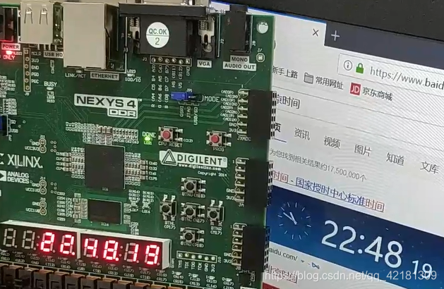
补充:
约束文件IO管脚设置没给出,然后这仅供刚开始学习verilog想做数字钟的同学或者其他人员参考,实现并不是很高效。源码可以随便用,转载请注明出处。

相关文章推荐
- 数字电路设计之堆栈的verilog实现
- 【续】FPGA电路逻辑的Verilog HDL编程方式设计与验证
- WBIA课程设计视频演示
- 模块管理常规功能自己定义系统的设计与实现(53--演示程序和视频解说 )
- 02-FPGA设计流程介绍——小梅哥FPGA设计思想与验证方法视频教程配套文档
- OpenRisc-63-OpenRISC开发板O_board的设计,实现,调试与验证
- Verilog设计与验证 学习笔记二
- 基于达芬奇技术的数字视频系统设计与实现
- 使用silverlight构建一个工作流设计器(八)(附源代码下载、在线演示、视频教程)
- 数字电路设计之32位先进进位加法器的verilog实现
- Verilog设计与验证 学习笔记4 Testbench编写
- 用verilog设计一数字钟系统
- 03-组合逻辑电路设计之译码器——小梅哥FPGA设计思想与验证方法视频教程配套文档
- 数字电路设计之verilog 原语
- Verilog设计与验证 学习笔记三
- 「智能车」视频讲解:智能小车设计方案演示
- Verilog HDL 与数字电路设计
- Verilog与FPGA数字系统设计学习笔记(一)——EDA技术概述与fpga概述
- 使用silverlight构建一个工作流设计器(十一)(附源代码下载、在线演示、视频教程)
- verilog 数字系统设计教程 读书笔记(1)