Source Address:
http://masteringelectronicsdesign.com/the-non-inverting-amplifier-output-resistance/ It is customary to consider the output resistance of the non-inverting amplifier as being zero, but why is that? An Op Amp’s own output resistance is in the range of tens of ohms. Still, when we connect the Op Amp in a feedback configuration, the output resistance decreases dramatically. Why?
To answer these questions, let’s calculate the output resistance of the non-inverting amplifier.
It is widely accepted that the output resistance of a device can be calculated using a theoretical test voltage source connected at the device output. The input, or inputs, are connected to ground. Nevertheless, instead of using this method, let’s try a different one: The small signal variation method.
Figure 1 shows the non-inverting amplifier, which drives a load, RL. This circuit has an equivalent Thevenin source as in Figure 2.
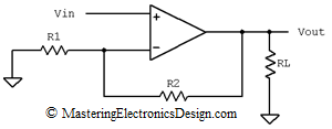
Figure 1The Non-Inverting Amplifier Output Resistance
by Adrian S. Nastase
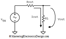
Figure 2From Figure 2, one can see that the output voltage, Vout, can be written as

| (1) |
If we keep VTH constant and apply small variations to Vout, by varying RL for example, the Vout variation, noted ΔVout can be written as follows:

| (2) |
Equation (2) shows that, when the load current increases, the load voltage decreases due to the output resistance. They vary in opposite direction and that is why the negative sign that appears in the Rout calculations is canceled out.
Equation (2) also tells us that we can use a small signal variation method to determine Rout. If, instead of ΔVout and ΔIout we write the small signal notation vout and iout, the output resistance becomes

| (3) |
Let’s apply this method to the non-inverting amplifier.
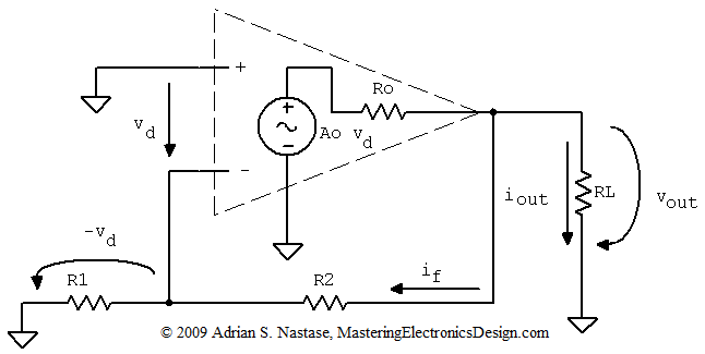
Figure 3An ideal Op Amp can be represented as a dependent source as in Figure 3. The output of the source has a resistor in series, Ro, which is the Op Amp’s own output resistance. The dependent source is Ao vd, where Ao is the Op Amp open-loop gain and vd is the differential input voltage. The input differential resistance, between the Op Amp inputs, is considered high, so I removed it for simplicity. The same with the common mode input resistances, between the non-inverting input and ground and the inverting input and ground. The non-inverting input is connected to ground, because a fixed value voltage source does not bring any change from a small-signal variation point of view. Thus, we are in line with the general rule that the output resistance of a circuit is calculated with the circuit inputs connected to ground.
Inspecting the loop made by Ao vd, Ro, and RL, vout can be expressed as in the following equation.

| (4) |
where iout is the small variation load current and if is the small variation feedback current.
The differential voltage vd appears across R1, but with negative sign, so if is

| (5) |
And vout becomes

| (6) |
At the same time vd depends on vout.

| (7) |
After replacing vd in equation (6), the resulting mathematical expression depends on vout and iout as in equation (8).

| (8) |
Based on (3) and (8) Rout is

| (9) |
Ao is large, about 100000 or 100 dB. Therefore, the second term of the denominator is predominant.

| (10) |
This proves that the output resistance of the non-inverting amplifier is

| (11) |
where ACL=1+R2/R1 and it is the closed-loop gain of the non-inverting amplifier. For a proof of the closed loop gain read this article,
MasteringElectronicsDesign.com:How to Derive the Non-Inverting Amplifier Transfer Function.
As equation (11) shows, the output resistance of the non-inverting amplifier is several orders of magnitude smaller than that of the Op Amp, because Ro is divided by the operational amplifier open loop gain. Therefore, the non-inverting amplifier output resistance can be considered zero.