基于Matlab的MIMO通信系统仿真(上)
2014-07-07 10:54
573 查看
引言:
近日,博主与队友共同完成了小学期作业——“基于Matlab的MIMO通信系统仿真”,收获良多,特将其记录下来,与诸位分享。此主题分为上下两部分,第一部分主要涉及系统架构,第二部分侧重程序优化。若能帮助读者一二,实属万幸。PS:信源、信道编码译码、调制解调由队友独立完成,特此声明。
系统结构:
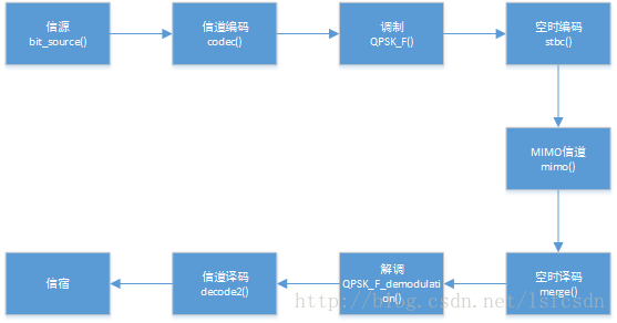
1、产生信源
function bit_in=bit_source(len)
% source generation
% this program generate the information source
% input:len ->the length of binary source which will be generate
% output:bit_in ->the binary source(01010....)
%% begin
bit_in=randi([0 1],1,len);
end
2、信道编码
卷积码function code= codec2( m ) % input:m -> bit source % output:code g0=[1 0 1 1 0 1 1 1 1]; %g0=[1 1 1 1 0 1 1 0 1]; g1=[1 1 0 1 1 0 0 1 1]; %g1=[1 1 0 0 1 1 0 1 1] g2=[1 1 1 0 0 1 0 0 1]; %g2=[1 0 0 1 0 0 1 1 1]; m0=conv(m,g0); m1=conv(m,g1); m2=conv(m,g2); l=length(m0); for i=1:l; code([3*i-2])=rem(m0([i]),2); code([3*i-1])=rem(m1([i]),2); code([3*i])=rem(m2([i]),2); end end
咬尾卷积码
function code= TailBiting_codec(m)
num=length(m);
constLen=7;
fprintf('信号长度%d\n',length(m));
%1/2咬尾卷积码:先输入尾部的码6比特,再输入正常码
c = [m(end-(constLen-2):end),m];
fprintf('补充尾部后信号长度%d\n',length(c));
%打孔器设计
%信号的长度必须是打孔向量长度的整数倍
%打孔长度本来为num/2*4 比特,但是由于信号多输入了6比特,会多产生12比特,所以打孔向量的长度为num/2*4 +12
%这12比特需要被被完全打掉
g = [1 0 1 1 0 1 1 ;1 1 1 1 0 0 1;1 1 1 0 1 0 1];
g =reshape(g,1,21);
for i = 1:(num/2)-1
g = [g,1 1 1 0 1 1 1 1 1 1 1 0 0 0 1 1 0 0 1 1 1];
end
%前面补0是为了打孔时,将前面的尾部生成的比特打掉(尾部本来是应该放在初始状态中的)
g = [zeros(1,12),g];
fprintf('打孔器的长度为 %d\n',length(g))
% 卷积编码
trellis = poly2trellis([7],[133 171 165]);
code= convenc(c, trellis);
fprintf('卷积编码输出长度为 %d\n',length(code))
end
3、调制(QPSK)
function QPSK = QPSK_F( m )
%UNTITLED 此处显示有关此函数的摘要
%   此处显示详细说明
num=length(m);
QPSK_in=-2*m+1;% 转换成双极性非归零码
QPSK_in_I=QPSK_in(1:2: (num-1));
QPSK_in_Q=QPSK_in(2:2:num);
QPSK_IQ=[QPSK_in_I;QPSK_in_Q];
p=[1,1i];
QPSK=p*QPSK_IQ;
end
4、stbc编码
function send = stbc( qpsk )
% stbc encoding for sending signal
% this program will encode the signal comes from modulation into matrix
% which is suitable for sending in a MIMO channel.this program assume the
% Alamouti,that means there are 2 sending antennas and 1 receiving antenna.
% input:qpsk ->the modulation signal come from function QPSK
% output:send ->the sending matrix suitable for MIMO channel.
% 2014/6/29 release lsf:optimize,abandon for circulation,adopt point
% operation instead;meanwhile,abandon 3D matrix,adopt 1D vector to storage
% the siganl,so the function mimo has been modify.
%% begin
% the overall thougth:fetch two signals from the sequence each time,and
% genarate a matrix by alamouti.for example,if you fecth x1 and x2,the
% genarated matrix will be [x1,-conj(x2);x2,conj(x1)].PS:conj means
% conjugate.

%% project A
% for circulation && 3D matrix;
% for i=1:2:size(qpsk,2)
%     X=[qpsk(i),-conj(qpsk(i+1));qpsk(i+1),conj(qpsk(i))];
%     send(:,:,(i+1)/2)=X;
% end
% matrix send is a 3D matrix,its third demension store the 2*2 matrix
% genarated by alamouti.In other words,send(:,:,1) means the alamouti
% matrix genatated by x1,x2,and sendd(:,:,2) is x3,x4 and so on.

%% project B
% point operation && vector
m=size(qpsk,2);     % function size return the length of modulation siganl.
n=2*m;              % n is the length of vector send,which is twice as large as size of qpsk
send=zeros(1,n);

% our goal is transfer qpsk siganl to another kind of signal to use
% diversity scheme.There are four steps to accomplish it.
% assume:
% qpsk=[x1,x2,x3,x4,......];
% send=[x1,x2,-conj(x2),conj(x1),x3,x4,-conj(x4),conj(x3),......];

% first:send(1)=qpsk(1),send(5)=qpsk(3)....and so on.
i=1:2:m;
j=1:4:n;
send(j)=qpsk(i);
% second:send(2)=qpsk(2),send(6)=qpsk(4).....and so on.
i=2:2:m;
j=2:4:n;
send(j)=qpsk(i);
% third:send(3)=-conj(qpsk(2)),send(7)=-conj(qpsk(4)),.....and so on.
i=2:2:m;
j=3:4:n;
send(j)=-conj(qpsk(i));
% fourth:send(4)=conj(qpsk(1)),send(8)=conj(qpsk(3)),.....and so on.
i=1:2:m;
j=4:4:n;
send(j)=conj(qpsk(i));
end
5、信道矩阵
注:此程序段出自:[韩]Yong Soo Cho等著,黄威等译,ISBN 《MIMO-OFDM无线通信技术及MATLAB实现》:978-7-121-20410-4 第66页~79页function hh=channel_coeff(NT,NR,N,Rtx,Rrx,type)
% correlated Rayleigh MIMO channel coefficient
% Inputs:
% bit :bit source;
% NT : number of transmitters
% NR : number of receivers
% N : legnth of channel matrix
% Rtx : correlation vector/matrix of Tx
% e.g.) [1 0.5], [1 0.5;0.5 1]
% Rrx : correlation vecotor/matrix of Rx
% type : correlation type: 'complex' or 'field'
% Outputs:
% hh : NR x NT x N correlated channel
%MIMO-OFDM Wireless Communications with MATLAB㈢ Yong Soo Cho, Jaekwon Kim, Won Young Yang and Chung G. Kang
%?2010 John Wiley & Sons (Asia) Pte Ltd
% uncorrelated Rayleigh fading channel, CN(1,0)
%% project A
h=sqrt(1/2)*(randn(NT*NR,N)+1i*randn(NT*NR,N)); %
if nargin<4, hh=h; return; end % Uncorrelated channel
if isvector(Rtx), Rtx=toeplitz(Rtx); end
if isvector(Rrx), Rrx=toeplitz(Rrx); end
% Narrow band correlation coefficient
if strcmp(type,'complex')
C = chol(kron(Rtx,Rrx))'; % Complex correlation
else
C = sqrtm(sqrt(kron(Rtx,Rrx))); % Power (field) correlation
end
% Apply correlation to channel matrix
hh=zeros(NR,NT,N);
for i=1:N, tmp=C*h(:,i); hh(:,:,i)=reshape(tmp,NR,NT); end
6、MIMO信道
2发1收
function [receive,receive_temp ]= mimo( send,H,SNR)
% solve the recevied signal
% this program shows what signal has been after they experience the MIMO
% channel,of course,there is also gaussian noise inevitable.
% input:send ->the matrix genarated by function stbc
% input:H -> the channel matrix
% output:receive ->the receive signal
%% begin
% the overall thougth:assume the send is X,H is H,receive is Y,gaussian
% noise is G,it is obvious that Y=H*X+G
% for i=1:1:size(send,3) %function size return how much sending matrix there are.
% temp=H*send(:,:,i);
% receive_temp(2*i-1)=temp(1);
% receive_temp(2*i)=temp(2);
% receive=awgn(receive_temp,10);
% %function awgn will add the gaussian nosie to the siganl,the second
% %parameter is the SNR)
% end
m=size(send,2);
n=m/2;
receive_temp=zeros(1,n);
i=1:4:m;
j=1:2:n;
receive_temp(j)=H(1).*send(i)+H(2).*send(i+1);
receive_temp(j+1)=H(1).*send(i+2)+H(2).*send(i+3);
receive=awgn(receive_temp,SNR);
end
2发2收
function [receive,receive_temp ]= mimo2( send,H,SNR)
% solve the recevied signal
% this program shows what signal has been after they experience the MIMO
% channel,of course,there is also gaussian noise inevitable.
% input:send ->the matrix genarated by function stbc
% input:H -> the channel matrix
% output:receive ->the receive signal
%% begin
% the overall thougth:assume the send is X,H is H
9eec
,receive is Y,gaussian
% noise is G,it is obvious that Y=H*X+G
% for i=1:1:size(send,3) %function size return how much sending matrix there are.
% temp=H*send(:,:,i);
% receive_temp(2*i-1)=temp(1);
% receive_temp(2*i)=temp(2);
% receive=awgn(receive_temp,10);
% %function awgn will add the gaussian nosie to the siganl,the second
% %parameter is the SNR)
% end
m=size(send,2);
n=m;
receive_temp=zeros(1,n);
i=1:4:m;
% j=1:4:n;
receive_temp(i)=H(1).*send(i)+H(2).*send(i+1);
receive_temp(i+1)=H(1).*send(i+2)+H(2).*send(i+3);
receive_temp(i+2)=H(3).*send(i)+H(4).*send(i+1);
receive_temp(i+3)=H(3).*send(i+2)+H(4).*send(i+3);
receive=awgn(receive_temp,SNR);
end
7、stbc译码
2发1收
function unjudge = merge( receive,H )
% merge the signal all recevied
% this program will merge all the signal which are recevied by receviers.
% input:receive ->the signal experienced MIMO channel
% input:H ->channel matrix
% output:unjudge ->the signal merged,it will be judged by demodulation.
% 2014/7/1 last lsf release
% 2014/7/1 optimize:abandon the for circulation and adopt the point
% operation;predistribute the space for vector unjudge;
%% begin
% hh=[conj(H(1)),H(2);conj(H(2)),-H(1)];
% for i=1:(size(receive,2)/2)
% unjudge_temp=hh*[receive(2*i-1),receive(2*i)]';
% unjudge(2*i-1)=unjudge_temp(1);
% unjudge(2*i)=unjudge_temp(2);
% end
m=size(receive,2);
% unjudge=zeros(m);
%unjudge_temp=zeros(m/2);
h1=conj(H(1));
h2=H(2);
h3=conj(H(2));
h4=-H(1);
unjudge=zeros(1,m);
i=1:2:m;
j=1:2:m;
unjudge(j)=h1.*receive(i)+h2.*receive(i+1);
unjudge(j+1)=h3.*receive(i)+h4.*conj(receive(i+1));
%unjudge_temp(j)=hh*[receive(2.*i-1),receive(2.*i)]';
%unjudge(2.*i-1:2.*i)=[hh.*[receive(2.*i-1),receive(2.*i)]']';
end
2发2收
function unjudge = merge2( receive,H )
% merge the signal all recevied
% this program will merge all the signal which are recevied by receviers.
% alamouti 2*2
% input:receive ->the signal experienced MIMO channel
% input:H ->channel matrix
% output:unjudge ->the signal merged,it will be judged by demodulation.
% 2014/7/1 last lsf release
% 2014/7/1 optimize:abandon the for circulation and adopt the point
% operation;predistribute the space for vector unjudge;
%% begin
% hh=[conj(H(1)),H(2);conj(H(2)),-H(1)];
% for i=1:(size(receive,2)/2)
% unjudge_temp=hh*[receive(2*i-1),receive(2*i)]';
% unjudge(2*i-1)=unjudge_temp(1);
% unjudge(2*i)=unjudge_temp(2);
% end
m=size(receive,2);
% unjudge=zeros(m);
%unjudge_temp=zeros(m/2);
unjudge=zeros(1,m/2);
unjudge_temp=zeros(1,m);
i=1:4:m;
%j=1:4:m;
unjudge_temp(i)=conj(H(1)).*receive(i)+H(2).*receive(i+1);
unjudge_temp(i+1)=conj(H(2)).*receive(i)+(-H(1)).*conj(receive(i+1));
unjudge_temp(i+2)=conj(H(3)).*receive(i+2)+H(4).*receive(i+3);
unjudge_temp(i+3)=conj(H(4)).*receive(i+2)+(-H(3)).*conj(receive(i+3));
i=1:4:m;
j=1:2:m/2;
unjudge(j)=unjudge_temp(i)+unjudge_temp(i+2);
unjudge(j+1)=unjudge_temp(i+1)+unjudge_temp(i+3);
%unjudge_temp(j)=hh*[receive(2.*i-1),receive(2.*i)]';
%unjudge(2.*i-1:2.*i)=[hh.*[receive(2.*i-1),receive(2.*i)]']';
end
8、解调
function QPSK_F_demo = QPSK_F_demodulation( QPSK,m)
%UNTITLED2 此处显示有关此函数的摘要
% 此处显示详细说明
% 2014/7/1 lsf last release
% 2014/7/1 optimize:use the function sign to adopt poing operation.
num=length(m);
QPSK_F_demo_I=1/2*(QPSK+conj(QPSK));
QPSK_F_demo_Q=-1/2*1i*(QPSK-conj(QPSK));
% for i=1:num/2;
% if QPSK_F_demo_I(i)>0
% QPSK_F_demo_I(i)=1;
% else
% QPSK_F_demo_I(i)=-1;
% end
% end
% for i=1:num/2;
% if QPSK_F_demo_Q(i)>0
% QPSK_F_demo_Q(i)=1;
% else
% QPSK_F_demo_Q(i)=-1;
% end
% end
i=1:num/2;
QPSK_F_demo_I(i)=sign(QPSK_F_demo_I(i));
QPSK_F_demo_Q(i)=sign(QPSK_F_demo_Q(i));
QPSK_F_demo(1:2:(num-1))=-1/2*(QPSK_F_demo_I-1);
QPSK_F_demo(2:2:num)=-1/2*(QPSK_F_demo_Q-1);
end
9、信道解码
卷积码解码
function decoded=decode2( code )
trellis = poly2trellis((9),[557 663 711]);
decoded = vitdec(code,trellis,8,'cont','hard'); % function vitdec consume the most time,but I have not found the method to optimize it,maybe the method doesn't exist.
decoded =decoded(9:size(decoded,2));
end
咬尾卷积码解码
function decode = TailBiting_decode( code,m )
%解码部分
%为了能在译码时获得咬尾卷积码的初始状态,把接收到的码子拷贝两份译码,第一份译码完毕以后,编码器的状态就与咬尾卷积码的起始状态相同了
C = [code,code];
num=length(m);
trellis = poly2trellis([7],[133 171 165]);
fprintf('双份比特的长度为%d\n',length(C))%144
g = [1 0 1 1 0 1 1 ;1 1 1 1 0 0 1;1 1 1 0 1 0 1];
g =reshape(g,1,21);
for i = 1:(num/2)-1
g = [g,1 1 1 0 1 1 1 1 1 1 1 0 0 0 1 1 0 0 1 1 1];
end
g = [zeros(1,12),g];
%相应的,解码器的打孔矩阵也要发生变化:
%当数据重复2份时,解码时的打孔矩阵并不是将原先的打孔矩阵重复而是,将编码打孔时的用来打掉咬尾的打孔部分去掉
g = [g(1+12:end),g(1+12:end)];
%输入解码器的比特长度应该是打孔矩阵的1的个数的整数倍
fprintf('打孔矩阵1的个数为%d\n',sum(g))
%译码
cR = vitdec(C, trellis, 6, 'trunc', 'hard');
fprintf('译码输出个数为%d\n',length(cR));
%解码时选择后面那一份的译码结果
decode = cR(length(cR)/2+7:end);
fprintf('最终结果个数为%d\n',length(decode));
end
10、系统主函数
%% desription
% this program simulate the BER of the whole system on different SNR
%% project A
% convolutional code && QPSK && 2*1 alamouti stbc && 2*1 rayleigh
% uncorrelated MIMO
%% begin
bit=bit_source(10000);
% genarate the bit source;
code=codec2(bit);
% source encoding
QPSK=QPSK_F(code);
% modulation
send=stbc(QPSK);
% stbc encoding
H=channel_coeff(2,1,1);
% channel matrix
BER=zeros(1,50);
matlabpool open local 3
parfor SNR=1:50
for i=1:100
[receive,receive_temp]=mimo(send,H,SNR);
% receive the signal
unjudge=merge(receive,H);
% merge all the signal received
QPSK_demo=QPSK_F_demodulation(unjudge,code);
% sink demodulation
decoded=decode2(QPSK_demo);
% decode the receive signal
BER(SNR)=BER(SNR)+sum(abs(bit-decoded))/size(bit,2);
% accumulate BER
end
BER(SNR)=BER(SNR)/100;
% slove the averge BER
end
matlabpool close;
11、误比特率仿真结果


相关文章推荐
- 基于多站纯方位粒子滤波跟踪系统及其 4000 matlab仿真
- 基于距离的粒子滤波跟踪系统及其matlab仿真
- 在Windows上基于VS2013搭建IT++库通信系统仿真平台(it++ 4.3.1&&vs2013)
- 基于HLA的分布式卫星通信仿真系统的构建
- 通信系统仿真速成第1天:QPSK调制与解调(Matlab仿真)
- 通信信号与系统分析(四 基于simulink仿真)
- 学习《基于MATLAB/Simulink的系统技术与仿真》1
- 基于MATLAB的QPSK通信系统
- 在Windows上基于VS2013搭建IT++库通信系统仿真平台(it++ 4.3.1&&vs2013)
- 基于google earth 的航路管理和飞行仿真系统
- 基于J2ME蓝牙的手机与计算机通信系统设计6
- 基于J2ME蓝牙的手机与计算机通信系统设计5
- 基于SOA的异构系统通信解决方案
- 数字光纤通信系统仿真软件的研究
- 基于J2ME蓝牙的手机与计算机通信系统设计1
- 基于J2ME蓝牙的手机与计算机通信系统设计4
- 构建VoIP Web callback系统 ---基于Web方式的phone2phone通信方式(2)
- 基于VxWorks的嵌入式系统复合通信模式
- 基于TMS320F2812的快速以太网通信系统平台
- 基于虚拟仪器技术的运行环境仿真系统的开发研究