【原创】The solutional manual of the Verilog HDL: A Guide to Digital Design and Synthesis (2nd)--ch09
2011-03-24 17:33
1911 查看
Chapter 9. Useful Modeling Techniques
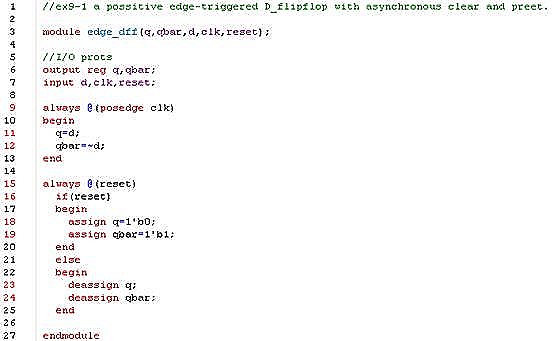
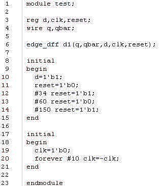
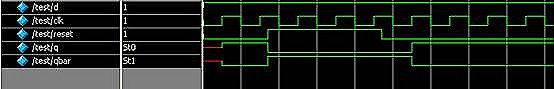
9.7 Exercises1. Using assign and deassign statements, design a positive edge-triggered D-flipflop with asynchronous clear(q=0) and preset (q=1).
my answer:
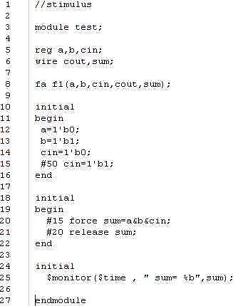
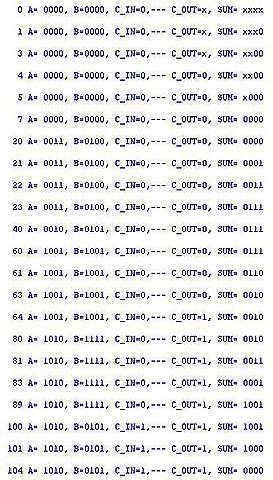
2. Using primitive gates, design a 1-bit full adder FA. Instantiate the full adder inside a stimulus module. Force the sum output to a & b & c_in for the time between 15 and 35 units.
my answer:


3. A 1-bit full adder FA is defined with gates and with delay parameters as shown below.
// Define a 1-bit full adder
module fulladd(sum,c_out,a,b,c_in);
parameter d_sum=0,d_cout=0;
//I/O port declarations
output sum,c_out;
input a,b,c_in;
//Internal nets
wire s1,c1,c2;
//Instantiate logic gate primitives
xor(s1,a,b);
and(c1,a,b);
xor #(d_sum) (sum,s1,c_in); //delay on output sum is d_sum
and (c2,s1,c_in);
or #(d_out) (c_out,c2,c1); //delay on output c_out is d_cout
endmodule
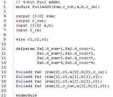
Define a 4-bit full adder fulladd4 as shown in example 5-8, but pass the following parameter values to the instances, using the two methods discussed in the book.
| Instance | Delay Values |
| fa0 | d_sum=1,d_cout-1 |
| fa1 | d_sum=2,d_cout=2 |
| fa2 | d_sum=2,d_cout=2 |
| fa3 | d_sum=3,d_cout=3 |
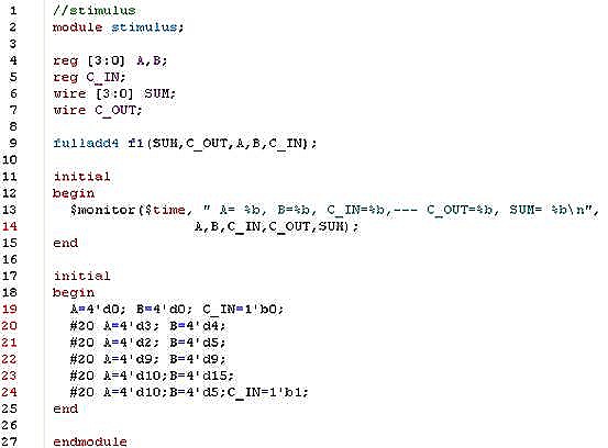
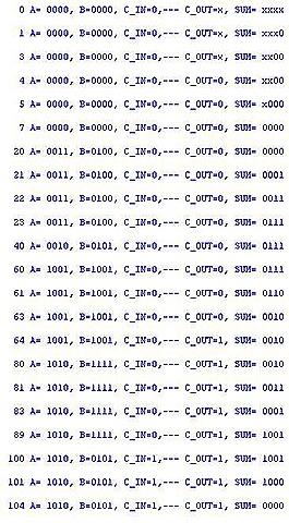
b. Build the fulladd4 with delay values passed to instances fa0, fa1, fa2, fa3 during instantiation. Resimulate the 4-bit adder, using the stimulus above. Check if the results are identical.
my answer:
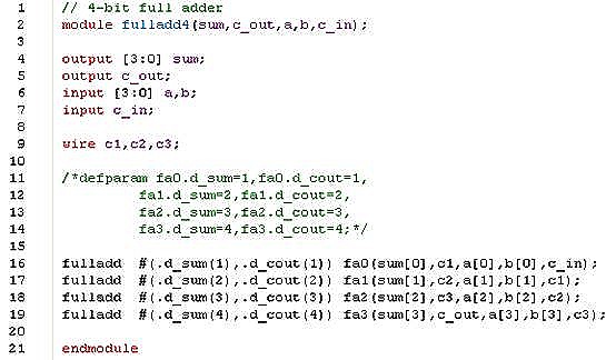
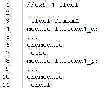
4. Create a design that uses the full adder example above. Use a conditional compilation (`ifdef). compile the fulladd4 with defparam statements if the text macro DPARAM is defined by the `define statement; otherwise, compile the fulladd4 with module instance parameter values.
my answer:
6. What will be the output of the $display statement shown below?

.
my answer:
# I am inside instance top.a1.b1
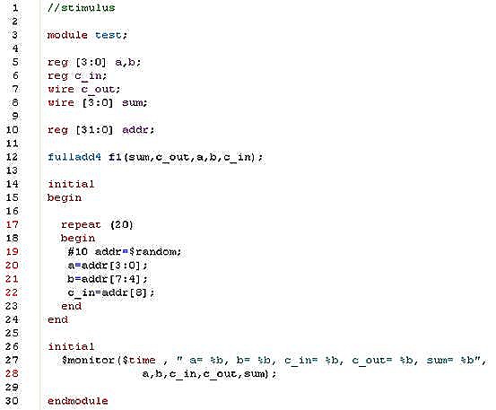
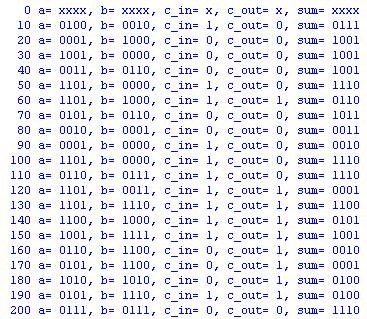
7. Consider the 4-bit full adder in example 6-4. Write a stimulus file to do random testing of the full adder. Use a random number generator to generate a 32-bit random number. Pick bit 3:0 and apply them to input a; pick bits 7:4 and apply them to input b. Use bit 8 and apply it to c_in. Apply 20 random test vectors and observe the output.
my answer:
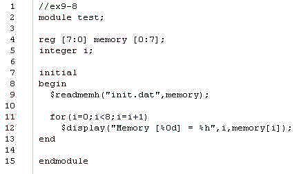
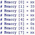
8. Use the 8-bit memory initialization example in example 9-14 . Modify the file to read data in hexadecimal. Write a new data file with the following addresses and data values. Unspecified locations are not initialized.
| Location Address | Data |
| 1 | 33 |
| 2 | 66 |
| 4 | z0 |
| 5 | 0z |
| 6 | 01 |
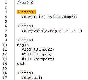
9. Write an initial block that controls the VCD file. The initial block must do the following:
l Set myfile.dmp as the output VCD file.
l Dump all variables two levels deep in module instance top.a1.b1.c1.
l Stop dumping to VCD at time 200.
l Start dumping to VCD at time 400.
l Stop dumping to VCD at time 500.
l Create a checkpoint. Dump the current value of all VCD variables to the dumpfile.
my answer:

相关文章推荐
- 【原创】The solutional manual of the Verilog HDL: A Guide to Digital Design and Synthesis (2nd)--ch02
- 【原创】The solutional manual of the Verilog HDL: A Guide to Digital Design and Synthesis (2nd)--ch08
- 【原创】The solutional manual of the Verilog HDL: A Guide to Digital Design and Synthesis (2nd)—ch07-III
- 【原创】The solutional manual of the Verilog HDL: A Guide to Digital Design and Synthesis (2nd)—ch07-I
- 【原创】The solutional manual of the Verilog HDL: A Guide to Digital Design and Synthesis (2nd)--ch03
- 【原创】The solutional manual of the Verilog HDL: A Guide to Digital Design and Synthesis (2nd)—ch07-II
- 【原创】The solutional manual of the Verilog HDL: A Guide to Digital Design and Synthesis (2nd)--ch06
- 【原创】The solutional manual of the Verilog HDL: A Guide to Digital Design and Synthesis (2nd)--ch12
- 【原创】The solutional manual of the Verilog HDL: A Guide to Digital Design and Synthesis (2nd)--ch10
- 【原创】The solutional manual of the Verilog HDL: A Guide to Digital Design and Synthesis (2nd)--ch05
- 【原创】The solutional manual of the Verilog HDL: A Guide to Digital Design and Synthesis (2nd)--ch04
- 【原创】The Design and Implementation of OO Model of Fetion Engine
- Understanding Windows CardSpace: An Introduction to the Concepts and Challenges of Digital Identitie
- A Designer's Guide to Adobe InDesign and XML: Harness the Power of XML to Automate your Print and We
- How to design DL model(2):Inception(v4)-ResNet and the Impact of Residual Connections on Learning
- Introduction to The Design and Analysis of Algorithms (1)
- Guide to Television and Video Technology, Fourth Edition: The Guide for the Digital Age - from HDTV,
- The Semantic Web : A Guide to the Future of XML, Web Services, and Knowledge Management
- The Essential Guide to User Interface Design: An Introduction to GUI Design Principles and Technique
- Design and Usability of Digital Libraries: Case Studies in the Asia Pacific