轻松学习自定义控件实现表钟效果-进阶篇新手必看,分分钟搞定自定义View
2016-09-25 18:57
375 查看
上篇介绍了组合自定义控件,那么今天来实现一个表钟效果。
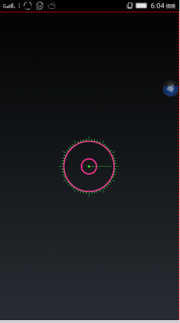
目前还没有让其动起来。下篇咱们将对其进行完善。咱们完整的效果,既然是钟,那他就得实现秒进分,分进时的功能,还得在刻度上面实现数字显示。
最终的效果是这样的。
其实,实现一个自定义控件其实并不难。在看本篇之前首先推荐大家先看上篇Android实现自定义View之组合控件(一)。
实现一个自定义控件,咱们需要重写的方法有onMeasure()尺寸测量方法,draw()绘画方法,还有构造方法。构造方法我们传入2个参数的就可以了。
首先,我们的思路是这样的。先在draw方法中画置2个空心圆,一个实心圆,还有一条线条。然后再绘画刻度。绘画刻度我是从最左端开始绘画的,学过三角函数的大家应该都有知道,正弦,余弦,正切。
其中的难点就在于计算,其实这些计算也是很简单的,下面我画个丑图给大家解释下如何实现坐标点的计算。
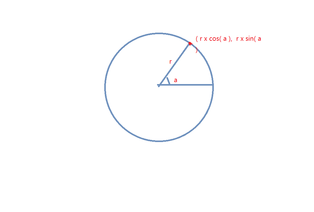
很方便我们就可以拿到刻度点的坐标。我们只需要知道圆的半径和角度,利用正余弦就可以解决。
我们知道一个表钟是360度。那么一个表钟有60个刻度。每个刻度占6度。
首先,我们新建议atttrs.xml文件。这个里面我们暂时只让它有一个改变圆的颜色的属性。
attrs.xml
下面我直接上代码,就不一一解释了。看过上一篇的童鞋相信大家能看得懂。
在这里咱们需要注意的地方是在测量方法里,由于咱们的自定义不是全屏的控件,所以咱们在使用的时候实际上不希望它自身就是一个match_parent的现象发生。所以在为wrap_content的时候,系统会自动帮我们设置为match_parent。所以此时咱们需要进行测量。也就是测量整个自定义控件的宽高。
在计算完了宽度和高度后,咱们需要使用setMeasuredDimension(width,height)方法将实际测量值设置进去。
实现了之后,咱们在布局文件中就可以使用了。
在布局文件中声明加入控件就可以了。
好了,到这里咱们也就实现了本篇自定义的效果。
目前还没有让其动起来。下篇咱们将对其进行完善。咱们完整的效果,既然是钟,那他就得实现秒进分,分进时的功能,还得在刻度上面实现数字显示。
最终的效果是这样的。
其实,实现一个自定义控件其实并不难。在看本篇之前首先推荐大家先看上篇Android实现自定义View之组合控件(一)。
实现一个自定义控件,咱们需要重写的方法有onMeasure()尺寸测量方法,draw()绘画方法,还有构造方法。构造方法我们传入2个参数的就可以了。
首先,我们的思路是这样的。先在draw方法中画置2个空心圆,一个实心圆,还有一条线条。然后再绘画刻度。绘画刻度我是从最左端开始绘画的,学过三角函数的大家应该都有知道,正弦,余弦,正切。
其中的难点就在于计算,其实这些计算也是很简单的,下面我画个丑图给大家解释下如何实现坐标点的计算。
很方便我们就可以拿到刻度点的坐标。我们只需要知道圆的半径和角度,利用正余弦就可以解决。
我们知道一个表钟是360度。那么一个表钟有60个刻度。每个刻度占6度。
首先,我们新建议atttrs.xml文件。这个里面我们暂时只让它有一个改变圆的颜色的属性。
attrs.xml
<?xml version="1.0" encoding="utf-8"?>
<resources>
<declare-styleable name = "Custom">
<attr name="color" format = "color"></attr>
</declare-styleable>
</resources>
下面我直接上代码,就不一一解释了。看过上一篇的童鞋相信大家能看得懂。
/**
*
*/
package com.mero.customclock.widget;
import android.annotation.SuppressLint;
import android.content.Context;
import android.content.res.TypedArray;
import android.graphics.Canvas;
import android.graphics.Paint;
import android.graphics.Rect;
import android.util.AttributeSet;
import android.util.DisplayMetrics;
import android.util.Log;
import android.view.Display;
import android.view.View;
import android.view.WindowManager;

import com.mero.customclock.R;

/**
*@项目名称: CustomClock
*@文件名称: CustomClockView.java
*@Date: 201
d217
6-9-25
*@Copyright: 2016 Technology Mero Inc. All rights reserved.
*注意:由Mero开发,禁止外泄以及使用本程序于其他的商业目的 。
*/
public class CustomClockView extends View{

private float mScreenWidth;
private float graduateStrokeShortLenth = 10;//每一短刻度的值
private float graduateStrokeLongLenth = 20;//每一长刻度的值
private Paint p;
private String TAG;
private Rect mBounds;
private int color;
/**
* @param context
* @param attrs
* @param defStyleAttr
*/
public CustomClockView(Context context, AttributeSet attrs, int defStyleAttr) {
super(context, attrs, defStyleAttr);
}

public CustomClockView(Context context) {
super(context);
}
/**
* @param context
* @param attrs
*/
public CustomClockView(Context context, AttributeSet attrs) {
super(context, attrs);
//得到我们的属性集对象
TypedArray typedArray = context.getTheme().obtainStyledAttributes(attrs, R.styleable.Custom, 0 ,0);
color = typedArray.getColor(R.styleable.Custom_color, 0xFF339933);
//得到屏幕的宽度
WindowManager wm = (WindowManager) context.getSystemService(Context.WINDOW_SERVICE);
Display display = wm.getDefaultDisplay();
DisplayMetrics metrics  = new DisplayMetrics();
display.getMetrics(metrics);
mScreenWidth = metrics.widthPixels;

}

/**
*
*/
private void init(int color) {
p = new Paint();
p.setAntiAlias(true);//设置为抗锯齿
p.setStyle(Paint.Style.STROKE);//设置为线条模式
p.setStrokeWidth(5);//设置线条宽度

}

@Override
public void draw(Canvas canvas) {
super.draw(canvas);
init(color);
mBounds = new Rect(0, 0, (int)mScreenWidth/3, (int)mScreenWidth/3);
//画大小外圈
p.setColor(0xffff3344);
canvas.drawCircle(mBounds.width()/2, mBounds.height()/2, 30, p);
canvas.drawCircle(mBounds.width()/2, mBounds.width()/2, 100, p);
//画中心圈
p.setColor(0xFF33ff33);
canvas.drawCircle(mBounds.width()/2, mBounds.height()/2, 2, p);
p.setColor(0xff229933);
//画分针
p.setColor(0xffffff44);
p.setStrokeWidth(2);
canvas.drawLine(mBounds.width()/2,  mBounds.height()/2, mBounds.width()/2+90,  mBounds.height()/2, p);
//画刻度
drawGraduate(canvas);
}

/**
*
*/
private void drawGraduate(Canvas canvas) {
//计算出初始刻度的坐标位置
float w0 = mBounds.width()/2;
float h0 = mBounds.height()/2;
//创建2只新画笔
Paint p1 = new Paint(Paint.ANTI_ALIAS_FLAG);//用来画长刻度
Paint p2 = new Paint(Paint.ANTI_ALIAS_FLAG);//用来画短刻度
p1.setColor(0xff229944);
p1.setStrokeWidth(2);
p2.setColor(0xff33ff44);
p2.setStrokeWidth(2);
/*画短刻度*/
for(int i = 0;i<60;i++){
float[] a0 = getNewDirect(i, w0, h0,graduateStrokeShortLenth);
float[] a1 = getNewDirect(i, w0, h0,graduateStrokeLongLenth);
if(i%5==0){
canvas.drawLine(w0+(float)(100*(Math.cos(Math.PI/180*i*6))), h0-(float)(100*Math.sin(Math.PI/180*i*6)), a1[0], a1[1], p1);
}else{
canvas.drawLine(w0+(float)(100*(Math.cos(Math.PI/180*i*6))), h0-(float)(100*Math.sin(Math.PI/180*i*6)), a0[0], a0[1], p2);
}
}

}
//计算得到新的尺寸
private float[] getNewDirect(int i,float w0,float h0,float graduateStrokeLenth){
float w1 = 0,h1 = 0;
w1 = (float) (w0+(100+graduateStrokeLenth)*Math.cos(Math.PI/180*i*6));
h1 = (float) (h0-(100+graduateStrokeLenth)*Math.sin(Math.PI/180*i*6));
return new float[]{w1,h1};
}
/* (non-Javadoc)
* @see android.view.View#onMeasure(int, int)
*/
@SuppressLint("DrawAllocation") @Override
protected void onMeasure(int widthMeasureSpec, int heightMeasureSpec) {
int widthMode = MeasureSpec.getMode(widthMeasureSpec);
int widthSize = MeasureSpec.getSize(widthMeasureSpec);
int heightMode = MeasureSpec.getMode(heightMeasureSpec);
int heightSize = MeasureSpec.getSize(heightMeasureSpec);
int width = 0;
int height = 0;
Rect mBounds1 = new Rect(0, 0, (int)mScreenWidth/3, (int)mScreenWidth/3);
Log.e(TAG, mBounds1+"");
if(widthMode==MeasureSpec.EXACTLY){
width = widthSize;
Log.e(TAG,"width in exactly: "+width);
}else{
width = mBounds1.width();
Log.e(TAG,"width in other: "+width);
}
if(heightMode==MeasureSpec.EXACTLY){
height = heightSize;
Log.e(TAG,"height in exactly: "+height);
}else{
height = mBounds1.height();
Log.e(TAG,"height in other: "+height);
}
setMeasuredDimension(width, height);
}
}
在这里咱们需要注意的地方是在测量方法里,由于咱们的自定义不是全屏的控件,所以咱们在使用的时候实际上不希望它自身就是一个match_parent的现象发生。所以在为wrap_content的时候,系统会自动帮我们设置为match_parent。所以此时咱们需要进行测量。也就是测量整个自定义控件的宽高。
在计算完了宽度和高度后,咱们需要使用setMeasuredDimension(width,height)方法将实际测量值设置进去。
实现了之后,咱们在布局文件中就可以使用了。
在布局文件中声明加入控件就可以了。
<RelativeLayout xmlns:android="http://schemas.android.com/apk/res/android"
xmlns:tools="http://schemas.android.com/tools"
xmlns:mero="http://schemas.android.com/com.mero.customclock"
android:layout_width="match_parent"
android:layout_height="match_parent"
>
<com.mero.customclock.widget.CustomClockView
android:layout_width="wrap_content"
android:layout_height="wrap_content"
mero:color="#FF0000"
android:layout_centerInParent="true"
/>

</RelativeLayout>
好了,到这里咱们也就实现了本篇自定义的效果。

相关文章推荐
- Android学习备忘020——android自定义ImageView实现缩放,回弹效果
- Android学习——自定义View实现蒙版新手引导(二)
- Android自定义控件系列六:自定义ViewGroup(一)实现ViewPager效果
- 手机卫士学习06-自定义滚动的TextView实现走马灯效果
- 【安卓自定义控件】自定义ViewGroup实现透明背景的ViewPager效果
- Android学习——自定义View实现蒙版新手引导
- Android 自定义View:教你轻松实现内存清理加速球的效果
- Android自定义控件系列六:自定义ViewGroup(一)实现ViewPager效果
- Android自定义控件系列六:自定义ViewGroup(一)实现ViewPager效果
- Android自定义控件系列五:自定义ViewGroup(一)实现ViewPager效果
- ios学习--iPhone遮盖系统栏,实现自定义效果的状态栏
- Android高手进阶教程(二十七)之---基于ViewFlipper实现的自定义新手指引控件.
- android 自定义ImageView实现图片手势滑动,多点触摸放大缩小效果
- 使用自定义RadioButton和ViewPager实现TabHost效果和带滑动的页卡效果。
- 自定义RadioButton和ViewPager实现TabHost带滑动的页卡效果
- Android自定义View实现HTML图文环绕效果
- Android自定义View实现HTML图文环绕效果
- 自定义TextView实现跑马灯效果
- Android自定义View实现HTML图文环绕效果
- Android自定义View实现转盘旋转的效果