关于OSPF(二)实验
2019-09-21 00:03
1581 查看
一、实验目的:
下面关于OSPF的实验,仔细看配置过程,以增加对OSPF的理解。
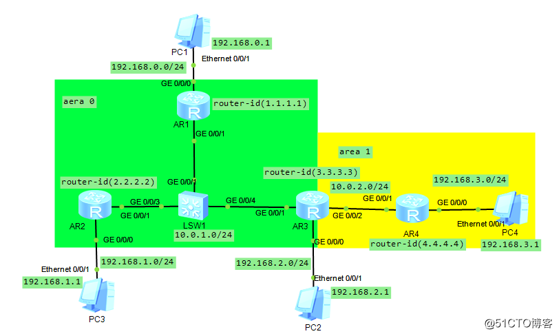
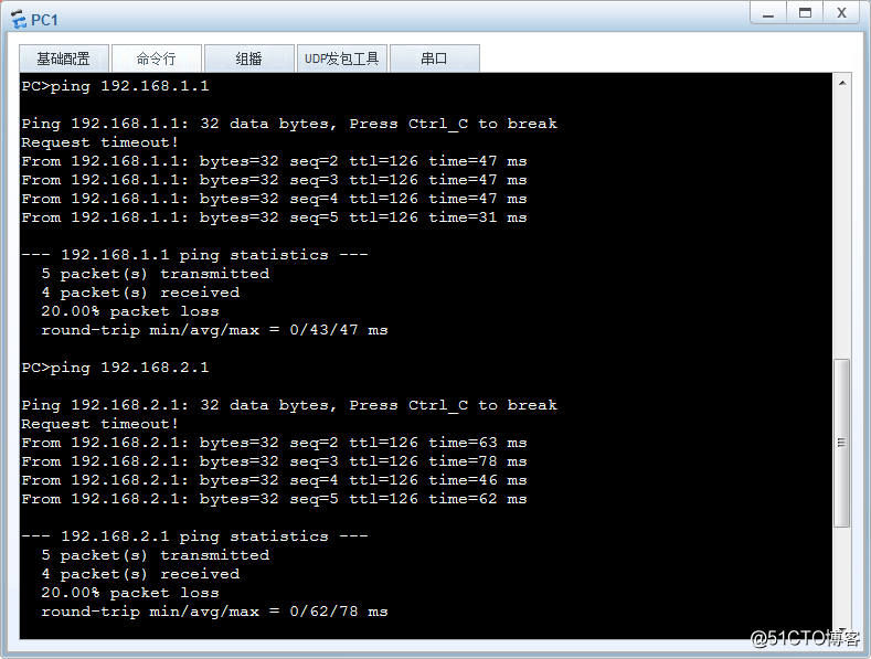
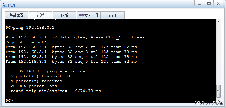
二、实现目标:
使用OSPF实现所有主机之间的通信

三、配置过程:
1、AR1的配置过程:

<Huawei>system-view    //进入配置模式
[Huawei]sysname AR1   //重命名为AR1
[AR1]interface GigabitEthernet 0/0/0   //进入路由器G0/0/0接口
[AR1-GigabitEthernet0/0/0]ip address 192.168.0.254 24   //配置接口IP地址
[AR1-GigabitEthernet0/0/0]interface GigabitEthernet 0/0/1 //进入G0/0/1接口
[AR1-GigabitEthernet0/0/1]ip address 10.0.1.1 24  //配置IP地址
[AR1-GigabitEthernet0/0/1]quit
[AR1]ospf router-id 1.1.1.1   //配置此路由器的router-id为1.1.1.1
[AR1-ospf-1]area 0    //设置为区域0 (0为主干区域)
[AR1-ospf-1-area-0.0.0.0]network 192.168.0.0 0.0.0.255
[AR1-ospf-1-area-0.0.0.0]network 10.0.1.0 0.0.0.255   //配置路由器两端的网
//段(网段后填写反掩码:反掩码就是转化为二进制后,1改为0,0改为1)上同
<AR1>save
The current configuration will be written to the device.
Are you sure to continue? (y/n)
:y
It will take several minutes to save configuration file, please wait.........
Configuration file had been saved successfully

2、AR2的配置过程:

<Huawei>system-view    //进入配置模式
[Huawei]sysname AR2   //重命名为AR2
[AR2]interface GigabitEthernet 0/0/0   //进入路由器G0/0/0接口
[AR2-GigabitEthernet0/0/0]ip address 192.168.1.254 24   //配置接口IP地址
[AR2-GigabitEthernet0/0/0]interface GigabitEthernet 0/0/1 //进入G0/0/1接口
[AR2-GigabitEthernet0/0/1]ip address 10.0.1.2 24  //配置IP地址
[AR2-GigabitEthernet0/0/1]quit
[AR2]ospf router-id 2.2.2.2   //配置此路由器的router-id为2.2.2.2
[AR2-ospf-1]area 0    //设置为区域0 (0为主干区域)
[AR2-ospf-1-area-0.0.0.0]network 192.168.1.0 0.0.0.255
[AR2-ospf-1-area-0.0.0.0]network 10.0.1.0 0.0.0.255   //配置路由器两端的网
//段(网段后填写反掩码:反掩码就是转化为二进制后,1改为0,0改为1)上同
<AR2>save
The current configuration will be written to the device.
Are you sure to continue? (y/n)
:y
It will take several minutes to save configuration file, please wait.........
Configuration file had been saved successfully

3、AR3(特殊)的配置过程:

<Huawei>system-view    //进入配置模式
[Huawei]sysname AR3   //重命名为AR3
[AR3]interface GigabitEthernet 0/0/0   //进入路由器G0/0/0接口
[AR3-GigabitEthernet0/0/0]ip address 192.168.2.254 24   //配置接口IP地址
[AR3-GigabitEthernet0/0/0]interface GigabitEthernet 0/0/1 //进入G0/0/1接口
[AR3-GigabitEthernet0/0/1]ip address 10.0.1.3 24  //配置接口IP地址
[AR3-GigabitEthernet0/0/1]interface GigabitEthernet 0/0/2 //进入G0/0/2接口
[AR3-GigabitEthernet0/0/2]ip address 10.0.2.1 24  //配置接口IP地址
[AR3-GigabitEthernet0/0/2]quit
[AR3]ospf router-id 3.3.3.3   //配置此路由器的router-id为3.3.3.3
[AR3-ospf-1]area 0    //设置为区域0 (0为主干区域)
[AR3-ospf-1-area-0.0.0.0]network 192.168.2.0 0.0.0.255
[AR3-ospf-1-area-0.0.0.0]network 10.0.1.0 0.0.0.255   //配置路由器两端的网
//段(网段后填写反掩码:反掩码就是转化为二进制后,1改为0,0改为1)上同
[AR3-ospf-1-area-0.0.0.0]quit
[AR3-ospf-1]area 1  //设置为区域1
[AR3-ospf-1-area-0.0.0.1]network 10.0.2.0 0.0.0.255 //与上同
<AR3>save
The current configuration will be written to the device.
Are you sure to continue? (y/n)
:y
It will take several minutes to save configuration file, please wait.........
Configuration file had been saved successfully

4、AR4的配置过程:

<Huawei>system-view    //进入配置模式
[Huawei]sysname AR4   //重命名为AR4
[AR4]interface GigabitEthernet 0/0/0   //进入路由器G0/0/0接口
[AR4-GigabitEthernet0/0/0]ip address 192.168.3.254 24   //配置接口IP地址
[AR4-GigabitEthernet0/0/0]interface GigabitEthernet 0/0/1 //进入G0/0/1接口
[AR4-GigabitEthernet0/0/1]ip address 10.0.2 2 24  //配置接口IP地址
[AR4-GigabitEthernet0/0/2]quit
[AR4]ospf router-id 4.4.4.4   //配置此路由器的router-id为4.4.4.4
[AR4-ospf-1]area 1    //设置为区域1
[AR4-ospf-1-area-0.0.0.1]network 192.168.3.0 0.0.0.255
[AR4-ospf-1-area-0.0.0.1]network 10.0.2.0 0.0.0.255   //配置路由器两端的网
//段(网段后填写反掩码:反掩码就是转化为二进制后,1改为0,0改为1)上同
<AR4>save
The current configuration will be written to the device.
Are you sure to continue? (y/n)
:y
It will take several minutes to save configuration file, please wait.........
Configuration file had been saved successfully
四、测试:
使用PC1 ping其他的三台主机

相关文章推荐
- 关于VRRP+OSPF的冗余口字型组网实验
- 关于eigrp,ospf,rip的综合实验
- 关于类型转换的实验
- 关于escape(), encodeURI()和encodeURIComponent()编码的几个实验
- 关于HTTP keep-alive的实验 - 黄亿华的个人页面 - 开源中国社区
- NA-NP-IE系列实验57:多区域OSPF 末节区域和完全末节区域
- 详解BSCI实验三、配置OSPF与EIGRP的路由再发布
- 关于ospf区域认证以及虚链路之间的配置问题
- 实验 单区域OSPF
- PHP关于变量声明的一个有趣的实验
- 关于Caffe之Contrastive + Softmax在MNIST上的实验
- 关于帧中继的点对点实验
- 21、OSPF配置实验之特殊区域totally stub
- ospf-LSA状态实验
- 关于workflow是否支持DOMINO的实验
- 28、OSPF配置实验之负载均衡
- Adapter:关于id和position的实验
- 关于实验常用验证方法
- Dev-C++下关于几种int类型格式符的实验
- 关于国嵌 实验2.5 网卡驱动移植 网卡地址 的问题