网络工程师TCNE阶段综合实验二详解
项目要求如下:
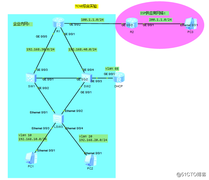
1.如图下所示蓝色区域为企业内网,红色区域为供应商网络;
2.运行MSTP协议,使得VLAN 10和vlan 20流量负载均衡;
3.SW1为vlan 10的主网关,SW1为vlan 20的备份网关;
4.SW2为vlan 20的主网关,SW2为vlan 10的备份网关;
5.DHCP服务器在vlan 66,网关在SW2上面;
6.企业内网运行静态路由协议或者OSPF路由协议;
7.PC1、PC2自动获取ip地址且可以与PC3互相ping通。
项目拓扑图如下:
第一步:配置基本网络;
SW1配置
sysname SW1
vlan batch 10 20 30 40 66
interface GigabitEthernet 0/0/1
port link-type trunk
port trunk allow-pass vlan all
interface GigabitEthernet 0/0/2
port link-type trunk
port trunk allow-pass vlan all
interface GigabitEthernet 0/0/3
port link-type access
port default vlan 30
interface Vlanif 30
ip address 192.168.30.2 24
SW2配置
sysname SW2
vlan batch 10 20 30 40 66
interface GigabitEthernet 0/0/1
port link-type trunk
port trunk allow-pass vlan all
interface GigabitEthernet 0/0/2
port link-type trunk
port trunk allow-pass vlan all
port link-type access
port default vlan 40
interface GigabitEthernet 0/0/3
port link-type access
port default vlan 66
interface GigabitEthernet 0/0/4
port link-type access
port default vlan 40
interface Vlanif 40
ip address 192.168.40.2 24
SW3配置
sysname SW3
vlan batch 10 20
interface Ethernet0/0/1
port link-type trunk
port trunk allow-pass vlan all
interface Ethernet0/0/2
port link-type trunk
port trunk allow-pass vlan all
interface Ethernet0/0/3
port link-type access
port default vlan 10
interface Ethernet0/0/4
port link-type access
port default vlan 20
R1配置
sysname R1
interface g0/0/0
ip address 192.168.30.1 24
interface g0/0/1
ip address 192.168.40.1 24
interface g0/0/2
ip address 100.1.1.2 24
quit
R2配置
sysname R2
interface g0/0/0
ip address 100.1.1.1 24
interface g0/0/1
ip address 200.1.1.254 24
quit
第二步:配置MSTP;
配置STP命令
SW1
stp region-configuration
region-name ntd
instance 10 vlan 10
instance 20 vlan 20
active region-configuration
quit
stp instance 10 priority 4096
stp instance 20 priority 8192
SW2
stp region-configuration
region-name ntd
instance 10 vlan 10
instance 20 vlan 20
active region-configuration
quit
stp instance 10 priority 8192
stp instance 20 priority 4096
SW3
stp region-configuration
region-name ntd
instance 10 vlan 10
instance 20 vlan 20
active region-configuration
quit
第三步:配置VRRP;
配置VRRP命令
SW1
interface Vlanif10
ip address 192.168.10.251 255.255.255.0
vrrp vrid 10 virtual-ip 192.168.10.250
vrrp vrid 10 priority 200
interface Vlanif20
ip address 192.168.20.251 255.255.255.0
vrrp vrid 10 virtual-ip 192.168.20.250
interface Vlanif66
ip address 192.168.66.251 255.255.255.0
SW2
interface Vlanif10
ip address 192.168.10.252 255.255.255.0
vrrp vrid 10 virtual-ip 192.168.10.250
interface Vlanif20
ip address 192.168.20.252 255.255.255.0
vrrp vrid 20 virtual-ip 192.168.20.250
vrrp vrid 10 priority 200
interface Vlanif66
ip address 192.168.66.252 255.255.255.0
第四步:配置DHCP;
配置DHCP命令
SW1
dhcp enable
interface Vlanif 10
dhcp select relay
dhcp relay server-ip 192.168.66.250
interface Vlanif 20
dhcp select relay
dhcp relay server-ip 192.168.66.250
SW2
dhcp enable
interface Vlanif 10
dhcp select relay
dhcp relay server-ip 192.168.66.250
interface Vlanif 20
dhcp select relay
dhcp relay server-ip 192.168.66.250
DHCP
sysname DHCP
dhcp enable
interface g0/0/0
ip address 192.168.66.250 24
dhcp select global
quit
ip pool p1
gateway-list 192.168.10.250
network 192.168.10.0 mask 255.255.255.0
excluded-ip-address 192.168.10.251 192.168.10.252
lease day 7 hour 0 minute 0
dns-list 8.8.8.8
ip pool p2
gateway-list 192.168.20.250
network 192.168.20.0 mask 255.255.255.0
excluded-ip-address 192.168.20.251 192.168.20.252
lease day 7 hour 0 minute 0
dns-list 8.8.8.8
第五步:配置OSPF;
配置OSPF命令
R1
ospf 1
area 0
network 192.168.30.0 0.0.0.255
network 192.168.40.0 0.0.0.255
ip route-static 0.0.0.0 0.0.0.0 100.1.1.1
SW1
ospf 1
area 0
network 192.168.10.0 0.0.0.255
network 192.168.20.0 0.0.0.255
network 192.168.30.0 0.0.0.255
network 192.168.66.0 0.0.0.255
SW2
ospf 1
area 0
network 192.168.10.0 0.0.0.255
network 192.168.20.0 0.0.0.255
network 192.168.40.0 0.0.0.255
network 192.168.66.0 0.0.0.255
DHCP
ospf 1
area 0
network 192.168.66.0 0.0.0.255
第六步:配置NAT;
配置NAT命令
acl number 2000
rule 10 permit source 192.168.0.0 0.0.255.255
interface GigabitEthernet0/0/2
nat outbound 2000
最后进行验证:
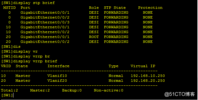
SW1上验证如下:
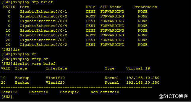
SW2上验证如下:
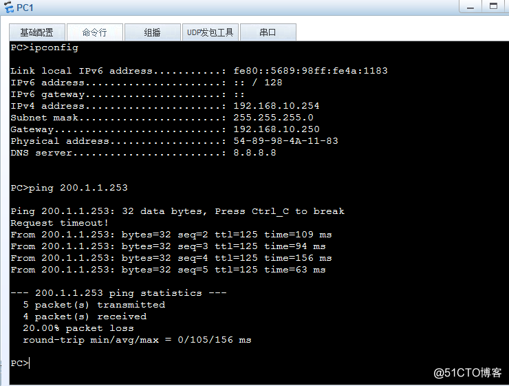
PC1验证如下:
项目实验完成!!!!

- 软考网络工程师实验指南(五)Windows Server 2003 DNS配置详解
- 软考网络工程师实验指南(一)Windows Server 2003的四种安装方式详解 推荐
- 软考网络工程师实验指南(七)Windows Server 2003 FTP服务器配置详解 推荐
- 软考网络工程师实验指南(一)Windows Server 2003的四种安装方式详解
- 华为三层交换机VRRP与DHCP综合实验详解
- 软考网络工程师实验指南(三)Windows Server 2003打印服务器配置详解
- OSPFv2的综合实验试题分析第2例(CCNP阶段) 推荐
- 软考网络工程师实验指南(四)Windows Server 2003 DHCP服务器配置详解
- ATEN—第四章 阶段综合实验
- OSPFv2的综合实验试题分析第1例(CCNP阶段) 推荐
- 第二次实验--算法基本功与综合思考
- 【软件开发综合实验】文本压缩软件
- CCNP实验精选之BGP大综合
- 专业阶段的六科我都考过了,综合算个P啊!
- 实验二 单臂路由及静态路由综合练习
- CCNA的一个综合实验(经典)
- 图的综合实验(Dijkstra算法)
- 【CCIE技术】WLAN安全技术综合分析详解概述