STM32F4 Timer Internal Trigger Connection
2015-08-25 23:11
183 查看

The Timers can be cascaded to make more complex timing relationships, or longer periods.
Internally only some timers can trigger others.
This is a Master/Slave relationship and is handled by the SMS register.
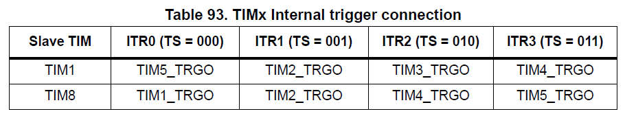
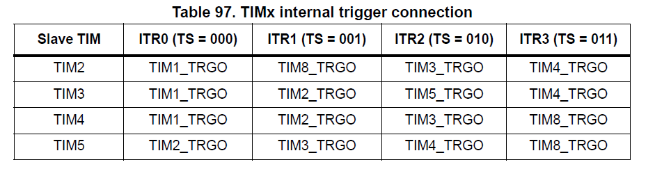
For example, you can see below that TIM8 can be triggerd by TIM1.

Uses TRGI to map.
One Timer can be used as the prescaler for another.
The first timer update_event, or output_compare signal is used as clock for the second.
The counter mode sets whether the update_event occurs on overflow and/or underflow of the Timer
Counter mode is set using the TIMx_CR1 reg and CMS bits as indicated in the example below.
Example for internal trigger
Internal trigger clock mode 1 (ITRx)TIM_CLK is replaced by ITRx_CLK which is the internal trigger freq mapped to timer Trigger input TRGI.
The counter mode indicates if the update_event is generated:
on overflow - if mode = up counting, the DIR bit is reset in TIMx_CR1
on underlfow - if mode = down counting, the DIR bit is set in TIMx_CR1
both - if mode is center aligned, the CMS bits are non zero
The update_event is also generated by:
software if the UG bit (Update Generation) is set in TIM_EGR reg.
update generation through the slave mode controller
refer to Timer app note: DM00042534.pdf
Timer synchronisation
A Master can control a slave Timer using a Trigger TRGO.A Timer is slaved if its ITRx is connected to a Slave and the Master is set to use TRGO
Trigger outputs from the Master can be selected from:
Reset:
UG bit from EGR reg is used as TRGO
Enable:
Counter enable is used as TRGO.
Used to start several timers at the same time or control window for Slave start
Update:
the update_event is TRGO.
e.g. a master timer can act as a prescaler for a slave timer.
Compare pulse:
as soon as a capure or match occurs TRGO goes high when CC1IF flag is to be set
OC1REF: use OC1REF as TRGO
OC2REF: use OC2REF as TRGO
OC3REF: use OC3REF as TRGO
OC4REF: use OC4REF as TRGO
Master mode:
Configure the TimerSelect Trigger output to be used
in CR2 reg - set MSM bits
Enable Master/slave mode
in SMCR reg - enable MSM bit
/*
* Trigger select mapping for slave timer from master timer.  This is
* unfortunately not very straightforward; there's no tidy way to do this
* algorithmically.  To avoid burning memory for a lookup table, use macros to
* compute the offset.  This also has the benefit that compilation will fail if
* an unsupported master/slave pairing is used.
*
* Slave        Master
*     1    15  2  3  4  (STM32F100 only)
*     2     9 10  3  4
*     3     9  2 11  4
*     4    10  2  3  9
*     9     2  3 10 11  (STM32L15x only)
*     --------------------
*     ts =  0  1  2  3
*/
#define STM32_TIM_TS_SLAVE_1_MASTER_15 0
#define STM32_TIM_TS_SLAVE_1_MASTER_2  1
#define STM32_TIM_TS_SLAVE_1_MASTER_3  2
#define STM32_TIM_TS_SLAVE_1_MASTER_4  3
#define STM32_TIM_TS_SLAVE_2_MASTER_9  0
#define STM32_TIM_TS_SLAVE_2_MASTER_10 1
#define STM32_TIM_TS_SLAVE_2_MASTER_3  2
#define STM32_TIM_TS_SLAVE_2_MASTER_4  3
#define STM32_TIM_TS_SLAVE_3_MASTER_9  0
#define STM32_TIM_TS_SLAVE_3_MASTER_2  1
#define STM32_TIM_TS_SLAVE_3_MASTER_11 2
#define STM32_TIM_TS_SLAVE_3_MASTER_4  3
#define STM32_TIM_TS_SLAVE_4_MASTER_10 0
#define STM32_TIM_TS_SLAVE_4_MASTER_2  1
#define STM32_TIM_TS_SLAVE_4_MASTER_3  2
#define STM32_TIM_TS_SLAVE_4_MASTER_9  3
#define STM32_TIM_TS_SLAVE_9_MASTER_2  0
#define STM32_TIM_TS_SLAVE_9_MASTER_3  1
#define STM32_TIM_TS_SLAVE_9_MASTER_10 2
#define STM32_TIM_TS_SLAVE_9_MASTER_11 3

相关文章推荐
- 高性能JavaScript 重排与重绘
- spring boot demo(spring jdbc访问数据)
- 苹果常见快捷方式
- 高性能JavaScript DOM编程
- Java 基础:变量 与 字符串
- 面向对象知识点梳理(2)
- 深入理解Surface系统
- c++ 纯虚函数与抽象类
- char与varchar的区别
- 页面架构
- Win7另存文件没有桌面的解决方法
- SVG学习笔录(二)
- Surround the Trees
- mybatis+mysql返回插入值后的主键id
- class_SeqList.
- 三种方法链接MySQL
- ios开发学习---一些概念的简介
- Filter的应用
- 手势识别器
- HDU 5349 MZL's simple problem 优先队列