dda的fpga实现(转载)
2015-08-05 09:13
169 查看
The general approach using DDAs will be to simulate a system of first-order differential equations, which can be nonlinear. Analog computers use operational amplifiers to do mathematical integration. We will use digital summers and registers. For any set of differential equations with state variables 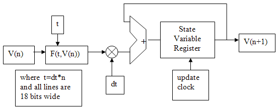 We also need a number representation. I chose 18-bit 2's complement with the binary point between bits 15 and 16 (with bit zero being the least significant). Bit 17 is the sign bit. The number range is thus
Second order system (damped spring-mass oscillator):As an example, consider the linear, second-order differential equation resulting from a damped spring-mass system: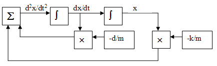 Converting this diagram to Verilog, the top-level module verilog code defines the 18-bit, signed, state variables and a clock divider variable (
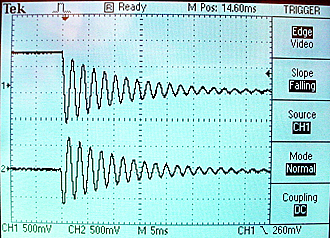 The whole project is zipped here. The design consumed 2% of the logic resources of the FPGA, 1% of the memory, and 4 out of 70 9-bit multipliers. You could threfore expect to put up to 50 integrators and 35 multipilers in a bigger design.
v1to
vm:
dv1/dt = f1(t,v1,v2,v3,...vm)
dv2/dt = f2(t,v1,v2,v3,...vm)
dv3/dt = f3(t,v1,v2,v3,...vm)
...
dvm/dt = fm(...)We will build the following circuitry to perform an Euler integration approximation to these equations in the form
v1(n+1) = v1(n) + dt*(f1(t,v1(n),v2(n),v3(n),...vm(n))
v2(n+1) = v2(n) + dt*(f2(t,v1(n),v2(n),v3(n),...vm(n))
v3(n+1) = v3(n) + dt*(f3(t,v1(n),v2(n),v3(n),...vm(n))
...
vm(n+1) = vm(n) + dt*(fm(...))
Where the variable values at time step
nare updated to form the values at time step
n+1. Each equation will require one integrator. The multiply may be replaced by a shift-right if
dtis chosen to be a power of two. Most of the design complexity will be in calculating
F(t,V(n)).
We also need a number representation. I chose 18-bit 2's complement with the binary point between bits 15 and 16 (with bit zero being the least significant). Bit 17 is the sign bit. The number range is thus -2.0to
+1.999985. This range fits well with the Audio codec which requires 16-bit 2's complement for output to the DAC. Conversion from the 18-bit to 16-bit just requires truncating the least significant two bits ([1:0]). A few numbers are shown in the table below. Note that the underscore character in the hexidecimal form is allowed in verilog to improve readability.
| [align=center]Decimal number[/align] | 18-bit 2's comprepresentation |
| [align=center]1.0[/align] | [align=center]18'h1_0000[/align] |
| [align=center]0.5[/align] | [align=center]18'h0_8000[/align] |
| [align=center]0.25[/align] | [align=center]18'h0_4000[/align] |
| [align=center]0[/align] | [align=center]18'h0_0000[/align] |
| [align=center]-0.25[/align] | [align=center]18'h3_c000[/align] |
| [align=center]-0.5[/align] | [align=center]18'h3_8000[/align] |
| [align=center]-1.0[/align] | [align=center]18'h3_0000[/align] |
| [align=center]-1.5[/align] | [align=center]18'h2_8000[/align] |
| [align=center]-2.0[/align] | [align=center]18'h2_0000[/align] |
d2x/dt2 = -k/m*x-d/m*(dx/dt)where k is the spring constant, d the damping coefficient, m the mass, and x the displacement. We will simulate this by converting the second-order system into a coupled first-order system. If we let
v1=xand
v2=dx/dtthen the second order equation is equivalent to
dv1/dt = v2dv2/dt = -k/m*v1-d/m*v2These equations can be solved by wiring together two integrators, two multipliers and an adder as shown below. In the past this would have been done by using operational amplifiers to compute each mathematical operation. Each integrator must be supplied with an initial condition.
Converting this diagram to Verilog, the top-level module verilog code defines the 18-bit, signed, state variables and a clock divider variable (count). The clocked section resets and updates the state variables. The combinatorial statements compute the Euler approximation to the
F(t,V(n)). The separate multiply module ensures that the multiplies will be instantiated as hardware multipliers. The Audio_DAC_ADC module was modifed to allow either ADC-to-DAC passthru or to connect the computation output to the DAC, depending on the position of SW17. SW17 up connects the computation.
/state variablesreg signed [17:0] v1, v2 ;wire signed [17:0] v1new, v2new ;//signed mult outputwire signed [17:0] v1xK_M, v2xD_M ;// the clock dividerreg [4:0] count;//Update state variables of simulation of spring- massalways @ (posedge CLOCK_50)begincount <= count + 1;if (KEY[3]==0) //resetbeginv1 <= 32'h10000 ; //v2 <= 32'h00000 ;//count <= 0;endelse if (count==0)beginv1 <= v1new ;v2 <= v2new ;endend// Compute new F(t,v) with dt = 2>>9// v1(n+1) = v1(n) + dt*v2(n)assign v1new = v1 + (v2>>>9);// v2(n+1) = v2(n) + dt*(-k/m*v1(n) - d/m*v2(n))signed_mult K_M(v1xK_M, v1, 18'h10000);signed_mult D_M(v2xD_M, v2, 18'h00800);assign v2new = v2 - ((v1xK_M + v2xD_M)>>>9);module signed_mult (out, a, b);output [17:0] out;input signed [17:0] a;input signed [17:0] b;wire signed [17:0] out;wire signed [35:0] mult_out;assign mult_out = a * b;assign out = {mult_out[35], mult_out[32:16]};endmoduleTime scaling the solution requires consideration of the value of dtand the update rate (
CLOCK_50/(clock divider)) of the state variables. As shown in the code, the clock divider variable (
count) is 5-bits wide, so it will overflow and cause an update every 32
CLOCK_50cycles. If the time step, dt=2-9, then 29 steps must equal one time unit. 29 steps at an update rate of 5*107/32 yields a time unit of 0.328 mSec. A k/m=1 implies a period of 6.28 time units per cycle, so one cycle in this case would be 2.06 mSec. corresponding to 486 Hz.If the calculation is scaled in time to be in the audio range, then the audio DAC may be used to watch waveforms on an oscilloscope. For the damped spring-mass oscillator with a k/m=1, d/m=1/16, dt=2-8, and a clock rate of 5*108/64 I got the figure below. The top trace is v1 and the bottom is v2. The frequency computed from the time scaling considerations is 486 Hz, while the measured was 475 Hz. Reducing
dtto dt=2-9 (see paragraph above) and the clock divider to 32 made the measured frequency 486, matching the computed value. The better match with smaller
dtillustrates that the integration is approximate.
The whole project is zipped here. The design consumed 2% of the logic resources of the FPGA, 1% of the memory, and 4 out of 70 9-bit multipliers. You could threfore expect to put up to 50 integrators and 35 multipilers in a bigger design.

相关文章推荐
- css 多行显示省略号....
- 南邮 OJ 1127 Stick
- struts 工作流程
- hulu面试经验
- Runtime获取网络状态
- StrategySelectionException异常
- PostgreSQL源码分析之shared buffer与磁盘文件
- Android 布局文件
- 二三四五六章作业
- 06-js禁止回车提交表单
- 南邮 OJ 1126 GCD
- C 语言中的好基友 数组和指针之三
- Android Studio系列教程五--Gradle命令详解与导入第三方包
- android view startAnimation后setVisibility没有效果
- importtsv工具使用笔记
- httpClient实现获取网络信息
- iOS 网络编程socket NSSteam的使用
- 2015年8月3日--oracle
- 在Eclipse中搭建Python开发环境
- 配置IIS7运行CGI脚本创建动态网页