ChrisRenke/DrawerArrowDrawable源码解析
2015-06-02 21:51
211 查看
转载请注明出处http://blog.csdn.net/crazy__chen/article/details/46334843
源码下载地址http://download.csdn.net/detail/kangaroo835127729/8765757
这次解析的控件DrawerArrowDrawable是一款侧拉抽屉效果的控件,在很多应用上我们都可以看到(例如知乎),控件的github地址为https://github.com/ChrisRenke/DrawerArrowDrawable
大家可以先来看一下控件的效果

这个控件的作者,也写过一篇文章对控件的制作过程做了说明,其中更多的是涉及箭头的变换具体算法,我在本文中将简化对算法的说明(因为比较复杂,我会提供给大家算法的思路)。如果大家对原文感兴趣,可以参考这个地址http://chrisrenke.com/drawerarrowdrawable/
另外还有一篇中文翻译http://www.eoeandroid.com/thread-561707-1-1.html?_dsign=e25beff0
下面我来说一下这个控件的具体制作方法。
首先我们可以看到,有一个侧拉抽屉的效果,这个效果是用android.support.v4包提供的android.support.v4.widget.DrawerLayout来实现的,对于这个控件,大家导入对应包,就可以使用。例如
由此可见,侧拉的效果是很容易实现(使用google提供的包)。
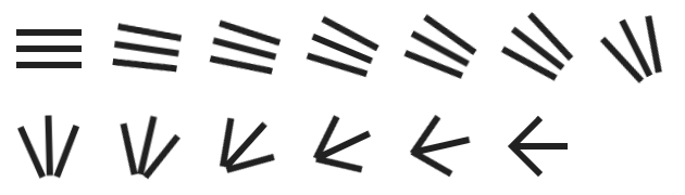
然而对比我们的DrawerArrowDrawable,会发现DrawerArrowDrawable有一个非常炫的效果,就是标题栏上的箭头变化。在初始状态,箭头是三条横线,当侧拉时,三条横线逐渐聚合成箭头,当侧拉返回时,又由箭头分散为三条横线。
本质上,这个箭头的实现,就是整个DrawerArrowDrawable的难点,大家可能一下子没有太好的思路。
我们先来看一下箭头变化的过程图
对于整个箭头整体,本质上是一个drawable,也就是说我们自定义一个drawable(这种方法我们在本专栏的其他文章也见过),修改它的ondraw方法,来实现一些复制的动画效果。
对于DrawerArrowDrawable,我们先关注三条横线中的第一条,对于第一条横线,有首尾两个点(这个两个点决定了这条横线)。下面的说明都是针对第一条横线而言(其他横线的原理和第一条是一样的)
横线在初始状态,有首尾两个点,称为a,b。a,b在整个箭头变化过程中,所在位置不断变化,从而构成一条轨迹(a,b各自一条)
我们将这个箭头状态分成三部分,如下
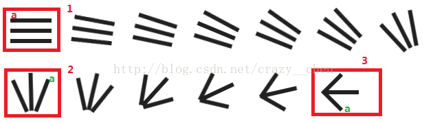
对于1,2,3三个状态,我们只考察a点,对于a点而言,状态1,到状态2,可以形成一个轨迹,是一个贝塞尔曲线(什么是贝塞尔曲线,大家可以自行百度,简而言之就是由一系列控制点(至少一个),可以确定两点之间的一条平滑曲线)。
有人会问,凭什么确定这是一条贝塞尔曲线呢,其实我们没有办法确定,但是我们可以确定一条贝塞尔曲线,使之近似等于a点的运动过轨,也就是说我们是把a点的轨迹抽象成函数,然后通过这个函数,我们就可以确定轨迹上每一点的坐标了。注意,这里的因果关系要弄明白,是现有轨迹,后有曲线,这个控件的作者,也是根据实际的轨迹,推算出轨迹的函数表达式的。
Ok,那么我们也容易知道,状态2到状态3,a点的轨迹,是另外一条贝塞尔曲线
同理,b点整个过程的轨迹,也就是两条贝塞尔曲线,而两点确定一条直线,根据a,b两个的轨迹,我们就能确定横线的轨迹了。
其他横线同理。所以要实现箭头的变换效果,我们只要根据贝塞尔曲线,不断绘制这个三天横线就可以了。
那么,对应到具体的java代码,我们应该怎么实现呢?下面开始结合源码进行说明。
首先来看构造函数和初始化
上面的代码有点多,先看开始部分,发现是一些初始化属性的代码,做了画笔初始化的工作,使用bounds保存了drawable的大小信息。
注意到,还计算了当前屏幕的密度,这个密度非常重要。为什么呢?
根据上面的说法,作者是根据轨迹,计算出曲线的,但是这个曲线的具体方程,跟作者用来计算的屏幕大小是有关的。例如作者屏幕上,状态2,a点的坐标是(10,10),那么在你的屏幕上,假设你的屏幕密度是作者的两倍,那么a的坐标,可能是(20,20),那么计算出来的曲线方程就不一样了。
所以这里记录了你的屏幕密度,和作者的屏幕密度相比,然后放大相应的倍数就可以了。
从源码中我们可以看到这样两个属性
OK,初始化以后,开始设定曲线,我拿第一条横线做例子
可以看到,首先new了一个first,然后moveTo()到一个位置(可想而知,这是状态1,a点的位置),然后调用rCubicTo()方法构造了贝塞尔曲线路径,这是一个三次贝塞尔曲线,关于rCubicTo()的具体用法,大家可以看api文档。这里(55.49f, -2.765f)对应的,就是状态2,a点的位置了,至于其他两个控制点,是由作者自己算出来的(计算方法上面已经说过了,就是模拟轨迹得到的)。
然后是second,其实就是状态2,到状态3了
接着调用scalePath()方法,其实是就是根据屏幕比例缩放了,上面已经提到过
最后,将两条路径合并成一个JoinedPath对象,由此可得,JoinedPath对象是保存了a从状态1到2的路径和a从状态2到3的路径
也即是JoinedPath保留了a的整个运动轨迹
例如我们有path路径a,长度是10(路径可能是曲线),我们用这个path创建一个PathMeasure对象,调用PathMeasure的getPosTan()方法,传入一个比例p(0-1),就可以得到在路径上,走了10*p距离的点的坐标。
那么对于a点,也就是说我们现在可以获得其轨迹上任意一点的坐标。
同理,对于b点
我们再次创建了first,second,然后合并出JoinedPath。
对于a,b两点的JoinedPath,我们又利用一个类来封装它们BridgingLine
到此位置,我们就可以画出a,b两点的横线了,但是a,b两个的坐标变化,是取决于parameter这个参数的
其实这个参数是我们主动传进去的,而这个参数大小,就等于侧拉抽屉的显示比例(当前显示面积,除以总面积)
这个是可想而知的,当这个侧拉抽屉被拉出来时,parameter应该等于1,表示去a,b点轨迹的最后一个点
而完全没有被拉出是,parameter应该等于0,表示去a,b点轨迹的第一个点
我们来看在外部怎么调用
对于这个监听器SimpleDrawerListener的onDrawerSlide()方法,当侧拉时,就会调用,传入slideOffset,也就是侧拉比例
可以知道slideOffset其实就是我们的parameter。
到此为止,这个箭头的效果就被我们实现了,接下只要在DrawerArrowDrawable的ondraw()方法里面,不断的绘制这三条曲线就好了
另外,这里做了一些近似处理,有时候移动停止时,slideOffset接近0或1,设置翻转
为什么要翻转呢,注意到,抽屉被拉出,和抽屉被缩入,箭头旋转的方向是不一样的,前者是0到180°,后者是180°到上360°
怎么实现呢,来看ondraw()方法就知道了
这个根据flip是否为真,从而决定是否翻转画布,翻转画布的效果的就是,使画布y坐标根据中心对称
对称以后,同样的效果0到180°,就会在画布上显示180°到上360°了,然后再讲画布恢复正常就可以了。
OK,DrawerArrowDrawable源码解析到这里就结束,看似简单的功能,却有复杂的逻辑。其实最复杂的逻辑在贝塞尔曲线的确定,本文提供了确定的思路,没有做具体的实现,大家可以参考控件原作者的文章。
源码下载地址http://download.csdn.net/detail/kangaroo835127729/8765757
这次解析的控件DrawerArrowDrawable是一款侧拉抽屉效果的控件,在很多应用上我们都可以看到(例如知乎),控件的github地址为https://github.com/ChrisRenke/DrawerArrowDrawable
大家可以先来看一下控件的效果
这个控件的作者,也写过一篇文章对控件的制作过程做了说明,其中更多的是涉及箭头的变换具体算法,我在本文中将简化对算法的说明(因为比较复杂,我会提供给大家算法的思路)。如果大家对原文感兴趣,可以参考这个地址http://chrisrenke.com/drawerarrowdrawable/
另外还有一篇中文翻译http://www.eoeandroid.com/thread-561707-1-1.html?_dsign=e25beff0
下面我来说一下这个控件的具体制作方法。
首先我们可以看到,有一个侧拉抽屉的效果,这个效果是用android.support.v4包提供的android.support.v4.widget.DrawerLayout来实现的,对于这个控件,大家导入对应包,就可以使用。例如
<!-- Content -->
<android.support.v4.widget.DrawerLayout
android:id="@+id/drawer_layout"
android:layout_width="match_parent"
android:layout_height="0dp"
android:layout_weight="1"
>

<TextView
android:id="@+id/view_content"
android:layout_width="match_parent"
android:layout_height="match_parent"
android:gravity="center"
android:textColor="#000000"
android:text="@string/content_hint"
android:background="#ffffff"
/>

<TextView
android:id="@+id/drawer_content"
android:layout_width="240dp"
android:layout_height="match_parent"
android:layout_gravity="start"
android:gravity="center"
android:text="@string/drawer_hint"
android:textColor="@color/light_gray"
android:background="@color/darker_gray"
/>

</android.support.v4.widget.DrawerLayout>
上面的xml,其实就是定义了一个侧拉抽屉,其中在.DrawerLayout中的第一个控件,会被当成是抽屉,而第二个控件,会被当成主要内容。
由此可见,侧拉的效果是很容易实现(使用google提供的包)。
然而对比我们的DrawerArrowDrawable,会发现DrawerArrowDrawable有一个非常炫的效果,就是标题栏上的箭头变化。在初始状态,箭头是三条横线,当侧拉时,三条横线逐渐聚合成箭头,当侧拉返回时,又由箭头分散为三条横线。
本质上,这个箭头的实现,就是整个DrawerArrowDrawable的难点,大家可能一下子没有太好的思路。
我们先来看一下箭头变化的过程图
对于整个箭头整体,本质上是一个drawable,也就是说我们自定义一个drawable(这种方法我们在本专栏的其他文章也见过),修改它的ondraw方法,来实现一些复制的动画效果。
对于DrawerArrowDrawable,我们先关注三条横线中的第一条,对于第一条横线,有首尾两个点(这个两个点决定了这条横线)。下面的说明都是针对第一条横线而言(其他横线的原理和第一条是一样的)
横线在初始状态,有首尾两个点,称为a,b。a,b在整个箭头变化过程中,所在位置不断变化,从而构成一条轨迹(a,b各自一条)
我们将这个箭头状态分成三部分,如下
对于1,2,3三个状态,我们只考察a点,对于a点而言,状态1,到状态2,可以形成一个轨迹,是一个贝塞尔曲线(什么是贝塞尔曲线,大家可以自行百度,简而言之就是由一系列控制点(至少一个),可以确定两点之间的一条平滑曲线)。
有人会问,凭什么确定这是一条贝塞尔曲线呢,其实我们没有办法确定,但是我们可以确定一条贝塞尔曲线,使之近似等于a点的运动过轨,也就是说我们是把a点的轨迹抽象成函数,然后通过这个函数,我们就可以确定轨迹上每一点的坐标了。注意,这里的因果关系要弄明白,是现有轨迹,后有曲线,这个控件的作者,也是根据实际的轨迹,推算出轨迹的函数表达式的。
Ok,那么我们也容易知道,状态2到状态3,a点的轨迹,是另外一条贝塞尔曲线
同理,b点整个过程的轨迹,也就是两条贝塞尔曲线,而两点确定一条直线,根据a,b两个的轨迹,我们就能确定横线的轨迹了。
其他横线同理。所以要实现箭头的变换效果,我们只要根据贝塞尔曲线,不断绘制这个三天横线就可以了。
那么,对应到具体的java代码,我们应该怎么实现呢?下面开始结合源码进行说明。
首先来看构造函数和初始化
public DrawerArrowDrawable(Resources resources, boolean rounded) {
this.rounded = rounded;
float density = resources.getDisplayMetrics().density;
float strokeWidthPixel = STROKE_WIDTH_DP * density;
halfStrokeWidthPixel = strokeWidthPixel / 2;

linePaint = new Paint(Paint.SUBPIXEL_TEXT_FLAG | Paint.ANTI_ALIAS_FLAG);
/* 当画笔样式为STROKE或FILL_OR_STROKE时,设置笔刷的图形样式,如圆形样式
* Cap.ROUND,或方形样式Cap.SQUARE
*/
linePaint.setStrokeCap(rounded ? Cap.ROUND : Cap.BUTT);
//画笔颜色
linePaint.setColor(Color.BLACK);
//设置画笔的样式,为FILL,FILL_OR_STROKE,或STROKE,也就是画轮廓,而fill是填充
linePaint.setStyle(Paint.Style.STROKE);
//设置空心的边框宽度
linePaint.setStrokeWidth(strokeWidthPixel);

int dimen = (int) (DIMEN_DP * density);
bounds = new Rect(0, 0, dimen, dimen);

Path first, second;
JoinedPath joinedA, joinedB;

// Top 第一条横线
first = new Path();
first.moveTo(5.042f, 20f);
//实现贝塞尔曲线,(x1,y1) 为控制点,(x2,y2)为控制点,(x3,y3) 为结束点
first.rCubicTo(8.125f, -16.317f, 39.753f, -27.851f, 55.49f, -2.765f);
second = new Path();
second.moveTo(60.531f, 17.235f);
second.rCubicTo(11.301f, 18.015f, -3.699f, 46.083f, -23.725f, 43.456f);
scalePath(first, density);
scalePath(second, density);
joinedA = new JoinedPath(first, second);

first = new Path();
first.moveTo(64.959f, 20f);
first.rCubicTo(4.457f, 16.75f, 1.512f, 37.982f, -22.557f, 42.699f);
second = new Path();
second.moveTo(42.402f, 62.699f);
second.cubicTo(18.333f, 67.418f, 8.807f, 45.646f, 8.807f, 32.823f);
scalePath(first, density);
scalePath(second, density);
joinedB = new JoinedPath(first, second);
topLine = new BridgingLine(joinedA, joinedB);

// Middle 第二条
first = new Path();
first.moveTo(5.042f, 35f);
first.cubicTo(5.042f, 20.333f, 18.625f, 6.791f, 35f, 6.791f);
second = new Path();
second.moveTo(35f, 6.791f);
second.rCubicTo(16.083f, 0f, 26.853f, 16.702f, 26.853f, 28.209f);
scalePath(first, density);
scalePath(second, density);
joinedA = new JoinedPath(first, second);

first = new Path();
first.moveTo(64.959f, 35f);
first.rCubicTo(0f, 10.926f, -8.709f, 26.416f, -29.958f, 26.416f);
second = new Path();
second.moveTo(35f, 61.416f);
second.rCubicTo(-7.5f, 0f, -23.946f, -8.211f, -23.946f, -26.416f);
scalePath(first, density);
scalePath(second, density);
joinedB = new JoinedPath(first, second);
middleLine = new BridgingLine(joinedA, joinedB);

// Bottom 第三条
first = new Path();
first.moveTo(5.042f, 50f);
first.cubicTo(2.5f, 43.312f, 0.013f, 26.546f, 9.475f, 17.346f);
second = new Path();
second.moveTo(9.475f, 17.346f);
second.rCubicTo(9.462f, -9.2f, 24.188f, -10.353f, 27.326f, -8.245f);
scalePath(first, density);
scalePath(second, density);
joinedA = new JoinedPath(first, second);

first = new Path();
first.moveTo(64.959f, 50f);
first.rCubicTo(-7.021f, 10.08f, -20.584f, 19.699f, -37.361f, 12.74f);
second = new Path();
second.moveTo(27.598f, 62.699f);
second.rCubicTo(-15.723f, -6.521f, -18.8f, -23.543f, -18.8f, -25.642f);
scalePath(first, density);
scalePath(second, density);
joinedB = new JoinedPath(first, second);
bottomLine = new BridgingLine(joinedA, joinedB);
}
上面的代码有点多,先看开始部分,发现是一些初始化属性的代码,做了画笔初始化的工作,使用bounds保存了drawable的大小信息。
注意到,还计算了当前屏幕的密度,这个密度非常重要。为什么呢?
根据上面的说法,作者是根据轨迹,计算出曲线的,但是这个曲线的具体方程,跟作者用来计算的屏幕大小是有关的。例如作者屏幕上,状态2,a点的坐标是(10,10),那么在你的屏幕上,假设你的屏幕密度是作者的两倍,那么a的坐标,可能是(20,20),那么计算出来的曲线方程就不一样了。
所以这里记录了你的屏幕密度,和作者的屏幕密度相比,然后放大相应的倍数就可以了。
从源码中我们可以看到这样两个属性
/**
* Paths were generated at a 3px/dp density; this is the scale factor for different densities.
* 路径是在3px/dp密度下生成的,这将是不同屏幕密度的缩放因子
*/
private final static float PATH_GEN_DENSITY = 3;

/**
* Paths were generated with at this size for {@link DrawerArrowDrawable#PATH_GEN_DENSITY}.
* 在PATH_GEN_DENSITY密度下,将生成这个尺寸的路径
*/
private final static float DIMEN_DP = 23.5f;这两个属性,就是作者的屏幕密度,和其密度下的尺寸大小,我们按比例缩放这个两个数字就可以了,下面会看到。OK,初始化以后,开始设定曲线,我拿第一条横线做例子
// Top 第一条横线
first = new Path();
first.moveTo(5.042f, 20f);
//实现贝塞尔曲线,(x1,y1) 为控制点,(x2,y2)为控制点,(x3,y3) 为结束点
first.rCubicTo(8.125f, -16.317f, 39.753f, -27.851f, 55.49f, -2.765f);
second = new Path();
second.moveTo(60.531f, 17.235f);
second.rCubicTo(11.301f, 18.015f, -3.699f, 46.083f, -23.725f, 43.456f);
scalePath(first, density);
scalePath(second, density);
joinedA = new JoinedPath(first, second);

first = new Path();
first.moveTo(64.959f, 20f);
first.rCubicTo(4.457f, 16.75f, 1.512f, 37.982f, -22.557f, 42.699f);
second = new Path();
second.moveTo(42.402f, 62.699f);
second.cubicTo(18.333f, 67.418f, 8.807f, 45.646f, 8.807f, 32.823f);
scalePath(first, density);
scalePath(second, density);
joinedB = new JoinedPath(first, second);
topLine = new BridgingLine(joinedA, joinedB);
可以看到,首先new了一个first,然后moveTo()到一个位置(可想而知,这是状态1,a点的位置),然后调用rCubicTo()方法构造了贝塞尔曲线路径,这是一个三次贝塞尔曲线,关于rCubicTo()的具体用法,大家可以看api文档。这里(55.49f, -2.765f)对应的,就是状态2,a点的位置了,至于其他两个控制点,是由作者自己算出来的(计算方法上面已经说过了,就是模拟轨迹得到的)。
然后是second,其实就是状态2,到状态3了
接着调用scalePath()方法,其实是就是根据屏幕比例缩放了,上面已经提到过
/**
* Scales the paths to the given screen density. If the density matches the
* {@link DrawerArrowDrawable#PATH_GEN_DENSITY}, no scaling needs to be done.
* 根据屏幕密度扩大路径尺寸
*/
private static void scalePath(Path path, float density) {
if (density == PATH_GEN_DENSITY) return;
Matrix scaleMatrix = new Matrix();
scaleMatrix.setScale(density / PATH_GEN_DENSITY, density / PATH_GEN_DENSITY, 0, 0);
path.transform(scaleMatrix);
}
最后,将两条路径合并成一个JoinedPath对象,由此可得,JoinedPath对象是保存了a从状态1到2的路径和a从状态2到3的路径
也即是JoinedPath保留了a的整个运动轨迹
/**
* Joins two {@link Path}s as if they were one where the first 50% of the path is {@code
* PathFirst} and the second 50% of the path is {@code pathSecond}.
* 合并两个路径,前50%为路径1,后50%为路径2
*/
private static class JoinedPath {
private final PathMeasure measureFirst;
private final PathMeasure measureSecond;
private final float lengthFirst;
private final float lengthSecond;

private JoinedPath(Path pathFirst, Path pathSecond) {
//PathMeasure类用于提供路径上的点坐标
measureFirst = new PathMeasure(pathFirst, false);
measureSecond = new PathMeasure(pathSecond, false);
lengthFirst = measureFirst.getLength();
lengthSecond = measureSecond.getLength();
}

/**
* Returns a point on this curve at the given {@code parameter}.
* For {@code parameter} values less than .5f, the first path will drive the point.
* For {@code parameter} values greater than .5f, the second path will drive the point.
* For {@code parameter} equal to .5f, the point will be the point where the two
* internal paths connect.
* 根据参数(比例)返回曲线上的点
* 如果参数parameter小于0.5,使用第一条路径计算,大于0.5,使用第二条路径计算
* 等于0.5,该点为两条路径的连接点
*/
private void getPointOnLine(float parameter, float[] coords) {
if (parameter <= .5f) {
parameter *= 2;
/*
* Pins distance to 0 <= distance <= getLength(),
* and then computes the corresponding position and tangent.
* Returns false if there is no path, or a zero-length path was specified,
* in which case position and tangent are unchanged.
* 根据距离(该距离范围在0到路径长度之间),计算路径上相应点的坐标和tan三角函数值,分别存储在
* 后两个参数之中(后两个参数都是拥有两个元素的一维数组)
*/
measureFirst.getPosTan(lengthFirst * parameter, coords, null);
} else {
parameter -= .5f;
parameter *= 2;
measureSecond.getPosTan(lengthSecond * parameter, coords, null);
}
}
}有上面代码可以看到,JoinedPath中有两个PathMeasure对象,PathMeasure是android提供的,用来获取路径上点的坐标的一个类例如我们有path路径a,长度是10(路径可能是曲线),我们用这个path创建一个PathMeasure对象,调用PathMeasure的getPosTan()方法,传入一个比例p(0-1),就可以得到在路径上,走了10*p距离的点的坐标。
那么对于a点,也就是说我们现在可以获得其轨迹上任意一点的坐标。
同理,对于b点
我们再次创建了first,second,然后合并出JoinedPath。
对于a,b两点的JoinedPath,我们又利用一个类来封装它们BridgingLine
topLine = new BridgingLine(joinedA, joinedB);来看BridgingLine
/**
* Draws a line between two {@link JoinedPath}s at distance {@code parameter} along each path.
* 根据两条路径上的点画一条直线
*/
private class BridgingLine {

private final JoinedPath pathA;
private final JoinedPath pathB;

private BridgingLine(JoinedPath pathA, JoinedPath pathB) {
this.pathA = pathA;
this.pathB = pathB;
}

/**
* Draw a line between the points defined on the paths backing {@code measureA} and
* {@code measureB} at the current parameter
* 根据当前参数,利用在两条路径上的两个点,画一条直线
*/
private void draw(Canvas canvas) {
pathA.getPointOnLine(parameter, coordsA);
pathB.getPointOnLine(parameter, coordsB);
if (rounded) insetPointsForRoundCaps();
canvas.drawLine(coordsA[0], coordsA[1], coordsB[0], coordsB[1], linePaint);
}

/**
* Insets the end points of the current line to account for the protruding
* ends drawn for {@link Cap#ROUND} style lines.
*
*/
private void insetPointsForRoundCaps() {
vX = coordsB[0] - coordsA[0];
vY = coordsB[1] - coordsA[1];

magnitude = (float) Math.sqrt((vX * vX + vY * vY));
paramA = (magnitude - halfStrokeWidthPixel) / magnitude;
paramB = halfStrokeWidthPixel / magnitude;

coordsA[0] = coordsB[0] - (vX * paramA);
coordsA[1] = coordsB[1] - (vY * paramA);
coordsB[0] = coordsB[0] - (vX * paramB);
coordsB[1] = coordsB[1] - (vY * paramB);
}
}BridgingLine没有太复杂的东西,其实就是提供了draw方法,用于画出a,b两点连成的横线。到此位置,我们就可以画出a,b两点的横线了,但是a,b两个的坐标变化,是取决于parameter这个参数的
pathA.getPointOnLine(parameter, coordsA);
pathB.getPointOnLine(parameter, coordsB);
那么这个参数又是什么决定的呢?
其实这个参数是我们主动传进去的,而这个参数大小,就等于侧拉抽屉的显示比例(当前显示面积,除以总面积)
这个是可想而知的,当这个侧拉抽屉被拉出来时,parameter应该等于1,表示去a,b点轨迹的最后一个点
而完全没有被拉出是,parameter应该等于0,表示去a,b点轨迹的第一个点
我们来看在外部怎么调用
final DrawerLayout drawer = (DrawerLayout) findViewById(R.id.drawer_layout);
        final ImageView imageView = (ImageView) findViewById(R.id.drawer_indicator);
        final Resources resources = getResources();

        drawerArrowDrawable = new DrawerArrowDrawable(resources);
        drawerArrowDrawable.setStrokeColor(resources.getColor(R.color.light_gray));
        imageView.setImageDrawable(drawerArrowDrawable);

        drawer.setDrawerListener(new DrawerLayout.SimpleDrawerListener() {
            @Override
            /*
             * Called when a drawer's position changes.//抽屉变化时调用
             * drawerView     The child view that was moved//被移动的子控件
             * slideOffset     The new offset of this drawer within its range, from 0-1//移动的比例
             */
            public void onDrawerSlide(View drawerView, float slideOffset) {
                offset = slideOffset;
                // Sometimes slideOffset ends up so close to but not quite 1 or 0.
                //有时候移动停止时,slideOffset接近0或1,设置翻转
                if (slideOffset >= .995) {
                  flipped = true;
                  drawerArrowDrawable.setFlip(flipped);
                } else if (slideOffset <= .005) {
                  flipped = false;
                  drawerArrowDrawable.setFlip(flipped);
                }

                drawerArrowDrawable.setParameter(offset);
        }
});从上面我们可以看到,我们为imageview设置了DrawerArrowDrawable对象,然后为DrawerLayout设置了一个监听器对于这个监听器SimpleDrawerListener的onDrawerSlide()方法,当侧拉时,就会调用,传入slideOffset,也就是侧拉比例
可以知道slideOffset其实就是我们的parameter。
到此为止,这个箭头的效果就被我们实现了,接下只要在DrawerArrowDrawable的ondraw()方法里面,不断的绘制这三条曲线就好了
另外,这里做了一些近似处理,有时候移动停止时,slideOffset接近0或1,设置翻转
为什么要翻转呢,注意到,抽屉被拉出,和抽屉被缩入,箭头旋转的方向是不一样的,前者是0到180°,后者是180°到上360°
怎么实现呢,来看ondraw()方法就知道了
@Override
public void draw(Canvas canvas) {
if (flip) {//是否翻转画布
canvas.save();
canvas.scale(1f, -1f, getIntrinsicWidth() / 2, getIntrinsicHeight() / 2);//中心点不变,y坐标对称
}

topLine.draw(canvas);
middleLine.draw(canvas);
bottomLine.draw(canvas);

if (flip) canvas.restore();
}
这个根据flip是否为真,从而决定是否翻转画布,翻转画布的效果的就是,使画布y坐标根据中心对称
对称以后,同样的效果0到180°,就会在画布上显示180°到上360°了,然后再讲画布恢复正常就可以了。
OK,DrawerArrowDrawable源码解析到这里就结束,看似简单的功能,却有复杂的逻辑。其实最复杂的逻辑在贝塞尔曲线的确定,本文提供了确定的思路,没有做具体的实现,大家可以参考控件原作者的文章。

相关文章推荐
- mongoDB 入门指南、示例
- 第十一周项目-1.1
- iOS_UITextField 基本操作
- 彻底搞定C指针
- Android广播BroadcastReceiver 一
- 基于java的双向链表实现方法
- mongoDB 介绍(特点、优点、原理)
- Cpp primer<<学习函数-实参类型转换、指向函数的指针_3
- 《转》收集最完整的arcgis拓扑处理
- Java UDP网络编程 简单实例
- android 自定义RadioButton样式
- C# Serializable
- KKT条件介绍
- Eclipse NDK 配置
- POj 1703 Find them, Catch them(关系并查集)
- Warning: The Copy Bundle Resources build phase contains this target's Info.plist file 'yintingting_baisi/Info.plist'.
- uva 10375 Choose and divide
- java多线程的实现和比较
- Interpolation Search与BinarySearch的比较
- c# 面试经验