OpenGL Perspective Projection Matrix
2014-01-04 18:18
375 查看
http://ksimek.github.io/2013/06/03/calibrated_cameras_in_opengl/
Author's note: some of this content appeared on my old blog as "Simulating Calibrated Cameras in OpenGL",
which contained some errors and missing equations and suffered from general badness. I hope you'll find this version to be less terrible.
Update (June 18, 2013): added negative signs to definitions of C' and D'.
Update (August 19, 2013): James Gregson
has posted an implementation in C++. I haven't tested it myself, but it looks quite nice.
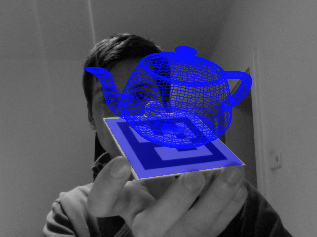
Simulating a calibrated camera for augmented reality.
Credit: thp4
You've calibrated your camera. You've decomposed it into intrinsic and extrinsic camera matrices. Now you need to use it to render a synthetic scene in OpenGL. You know the extrinsic matrix corresponds to the modelview matrix and the intrinsic is the projection
matrix, but beyond that you're stumped. You remember something about
camera matrix aren't obvious and it looks like you'll have to ignore your camera's axis skew. You may be asking yourself, "I have a matrix, why can't I just use it?"
You can. And you don't have to jettison your axis skew, either. In this article, I'll show how to use your intrinsic camera matrix in OpenGL with minimal modification. For illustration, I'll use OpenGL 2.1 API calls, but the same matrices can be sent to
your shaders in modern OpenGL.
glFrustum describes a perspective matrix that produces a perspective projection.
While this is true, it only tells half of the story.
In reality,
The former is a common operation in projective geometry, while the latter is OpenGL arcana, an implementation detail.
To give us finer-grained control over these operations, we'll separate projection matrix into two matricesPersp and
NDC:
Proj=NDC×Persp
Our intrinsic camera matrix describes a perspective projection, so it will be the key to thePersp matrix. For the
NDC matrix, we'll (ab)use OpenGL's
negative z-axis, so ifK33
is positive, vertices in front of the camera will have a negative w coordinate after projection. In principle, this is okay, butbecause
of how OpenGL performs clipping, all of these points will be clipped.
If K33
isn't -1, your intrinsic and extrinsic matrices need some modifications. Getting the camera decomposition right isn't trivial, so I'll refer the reader tomy earlier article
on camera decomposition, which will walk you through the steps. Part of the result will be the negation of the third column of the intrinsic matrix, so you'll see those elements negated below.
K=⎛⎝α00sβ0−x0−y0−1⎞⎠
For the second modification, we need to prevent losing Z-depth information, so we'll add an extra row and column to the intrinsic matrix.
Persp=⎛⎝⎜⎜⎜α000sβ00−x0−y0A−100B0⎞⎠⎟⎟⎟
where
AB=near+far=near∗far
The new third row preserve the ordering of Z-values while mapping -near and-far onto themselves (after normalizing by
w, proof left as an exercise). The result is that points between the clipping planes remain between clipping planes after multiplication byPersp.
A call to
glOrtho=⎛⎝⎜⎜⎜⎜⎜⎜⎜⎜⎜⎜2right−left00002top−bottom0000−2far−near0txtytz1⎞⎠⎟⎟⎟⎟⎟⎟⎟⎟⎟⎟
where
txtytz=−right+leftright−left=−top+bottomtop−bottom=−far+nearfar−near
When calling
B above. The choice of top, bottom, left, and right clipping planes correspond to the dimensions of the original image and the coordinate conventions used during calibration. For example, if your camera was calibrated from an image with dimensions
W×H
and its origin at the top-left, your OpenGL 2.1 code would be
Note that H is used as the "bottom" parameter and 0 is the "top," indicating a y-downward axis convention.
If you calibrated using a coordinate system with the y-axis pointing upward and the origin at the center of the image,
Note that there is a strong relationship between the
is equivalent to dividing left and right by two. This is the same relationship that exists in a pinhole camera between the camera's geometry and the geometry of its film--shifting the pinhole right is equivalent to shifting the film left;
doubling the focal length is equivalent to halving the dimensions of the film. Clearly the two-matrix representation of projection is redundant, but keeping these matrices separate allows us to maintain the logical separation between the camera geometry and
the image geometry.
and β
are set to near and s,x0
and y0
are zero. The resulting matrix is:
Proj=NDC∗Persp=⎛⎝⎜⎜⎜⎜⎜⎜⎜⎜⎜⎜2right−left00002top−bottom0000−2far−near0txtytz1⎞⎠⎟⎟⎟⎟⎟⎟⎟⎟⎟⎟∗⎛⎝⎜⎜near0000near0000A−100B0⎞⎠⎟⎟=⎛⎝⎜⎜⎜⎜⎜⎜⎜2nearright−left00002neartop−bottom00A′B′C′−100D′0⎞⎠⎟⎟⎟⎟⎟⎟⎟
where
A′B′C′D′=right+leftright−left=top+bottomtop−bottom=−far+nearfar−near=−2farnearfar−near
This is equivalent to
the matrix produced by glFrustum.
By tweaking the frame bounds we can relax the constraints imposed above. We can implement focal lengths other thannear by scaling the frame:
left′right′top′bottom′=(nearα)left=(nearα)right=(nearβ)top=(nearβ)bottom
Non-zero principal point offsets are achieved by shifting the frame window:
left′′right′′top′′bottom′′=left′−x0=right′−x0=top′−y0=bottom′−y0
Thus, with a little massaging,
so your scene is inside-out. The
previous article on camera decomposition should help you prevent this.
Alternatively, you can convert your rotation matrix to axis-angle form and use
this previous article for a longer discussion of the extrinsic matrix, including how to it with
a high poly count so the curved distortions appear smooth--does anyone have experience with this? In a future article, I'll cover how to accomplish stereo and head-tracked rendering using simple modifications to your intrinsic camera parameters.
Calibrated Cameras in OpenGL without glFrustum
June 03, 2013Author's note: some of this content appeared on my old blog as "Simulating Calibrated Cameras in OpenGL",
which contained some errors and missing equations and suffered from general badness. I hope you'll find this version to be less terrible.
Update (June 18, 2013): added negative signs to definitions of C' and D'.
Update (August 19, 2013): James Gregson
has posted an implementation in C++. I haven't tested it myself, but it looks quite nice.
Simulating a calibrated camera for augmented reality.
Credit: thp4
You've calibrated your camera. You've decomposed it into intrinsic and extrinsic camera matrices. Now you need to use it to render a synthetic scene in OpenGL. You know the extrinsic matrix corresponds to the modelview matrix and the intrinsic is the projection
matrix, but beyond that you're stumped. You remember something about
gluPerspective, but it only permits two degrees of freedom, and your intrinsic camera matrix has five. glFrustum looks promising, but the mapping between its parameters and the
camera matrix aren't obvious and it looks like you'll have to ignore your camera's axis skew. You may be asking yourself, "I have a matrix, why can't I just use it?"
You can. And you don't have to jettison your axis skew, either. In this article, I'll show how to use your intrinsic camera matrix in OpenGL with minimal modification. For illustration, I'll use OpenGL 2.1 API calls, but the same matrices can be sent to
your shaders in modern OpenGL.
glFrustum: Two Transforms in One
To better understand perspective projection in OpenGL, let's examineglFrustum. According to the OpenGL documentation,
glFrustum describes a perspective matrix that produces a perspective projection.
While this is true, it only tells half of the story.
In reality,
glFrustumdoes two things: first it performs perspective projection, and then it converts tonormalized device coordinates (NDC).
The former is a common operation in projective geometry, while the latter is OpenGL arcana, an implementation detail.
To give us finer-grained control over these operations, we'll separate projection matrix into two matricesPersp and
NDC:
Proj=NDC×Persp
Our intrinsic camera matrix describes a perspective projection, so it will be the key to thePersp matrix. For the
NDC matrix, we'll (ab)use OpenGL's
glOrthoroutine.
Step 1: Projective Transform
Our 3x3 intrinsic camera matrix K needs two modifications before it's ready to use in OpenGL. First, for proper clipping, the (3,3) element ofK must be -1. OpenGL's camera looks down thenegative z-axis, so ifK33
is positive, vertices in front of the camera will have a negative w coordinate after projection. In principle, this is okay, butbecause
of how OpenGL performs clipping, all of these points will be clipped.
If K33
isn't -1, your intrinsic and extrinsic matrices need some modifications. Getting the camera decomposition right isn't trivial, so I'll refer the reader tomy earlier article
on camera decomposition, which will walk you through the steps. Part of the result will be the negation of the third column of the intrinsic matrix, so you'll see those elements negated below.
K=⎛⎝α00sβ0−x0−y0−1⎞⎠
For the second modification, we need to prevent losing Z-depth information, so we'll add an extra row and column to the intrinsic matrix.
Persp=⎛⎝⎜⎜⎜α000sβ00−x0−y0A−100B0⎞⎠⎟⎟⎟
where
AB=near+far=near∗far
The new third row preserve the ordering of Z-values while mapping -near and-far onto themselves (after normalizing by
w, proof left as an exercise). The result is that points between the clipping planes remain between clipping planes after multiplication byPersp.
Step 2: Transform to NDC
The NDC matrix is (perhaps surprisingly) provided byglOrtho. ThePersp matrix converts a frustum-shaped space into a cuboid-shaped shape, while
glOrthoconverts the cuboid space to normalized device coordinates.
A call to
glOrtho(left, right, bottom, top, near, far)constructs the matrix:
glOrtho=⎛⎝⎜⎜⎜⎜⎜⎜⎜⎜⎜⎜2right−left00002top−bottom0000−2far−near0txtytz1⎞⎠⎟⎟⎟⎟⎟⎟⎟⎟⎟⎟
where
txtytz=−right+leftright−left=−top+bottomtop−bottom=−far+nearfar−near
When calling
glOrtho, the near and far parameters should be the same as those used to computeA and
B above. The choice of top, bottom, left, and right clipping planes correspond to the dimensions of the original image and the coordinate conventions used during calibration. For example, if your camera was calibrated from an image with dimensions
W×H
and its origin at the top-left, your OpenGL 2.1 code would be
glLoadIdentity();
glOrtho(0, W, H, 0, near, far);
glMultMatrix(persp);
Note that H is used as the "bottom" parameter and 0 is the "top," indicating a y-downward axis convention.
If you calibrated using a coordinate system with the y-axis pointing upward and the origin at the center of the image,
glLoadIdentity();
glOrtho(-W/2, W/2, -H/2, H/2, near, far);
glMultMatrix(persp);
Note that there is a strong relationship between the
glOrthoparameters and the perspective matrix. For example, shifting the viewing volume left by X is equivalent to shifting the principal point right by X. Doublingα
is equivalent to dividing left and right by two. This is the same relationship that exists in a pinhole camera between the camera's geometry and the geometry of its film--shifting the pinhole right is equivalent to shifting the film left;
doubling the focal length is equivalent to halving the dimensions of the film. Clearly the two-matrix representation of projection is redundant, but keeping these matrices separate allows us to maintain the logical separation between the camera geometry and
the image geometry.
Equivalence to glFrustum
We can show that the two-matrix approach above reduces to a single call toglFrustumwhen α
and β
are set to near and s,x0
and y0
are zero. The resulting matrix is:
Proj=NDC∗Persp=⎛⎝⎜⎜⎜⎜⎜⎜⎜⎜⎜⎜2right−left00002top−bottom0000−2far−near0txtytz1⎞⎠⎟⎟⎟⎟⎟⎟⎟⎟⎟⎟∗⎛⎝⎜⎜near0000near0000A−100B0⎞⎠⎟⎟=⎛⎝⎜⎜⎜⎜⎜⎜⎜2nearright−left00002neartop−bottom00A′B′C′−100D′0⎞⎠⎟⎟⎟⎟⎟⎟⎟
where
A′B′C′D′=right+leftright−left=top+bottomtop−bottom=−far+nearfar−near=−2farnearfar−near
This is equivalent to
the matrix produced by glFrustum.
By tweaking the frame bounds we can relax the constraints imposed above. We can implement focal lengths other thannear by scaling the frame:
left′right′top′bottom′=(nearα)left=(nearα)right=(nearβ)top=(nearβ)bottom
Non-zero principal point offsets are achieved by shifting the frame window:
left′′right′′top′′bottom′′=left′−x0=right′−x0=top′−y0=bottom′−y0
Thus, with a little massaging,
glFrustumcan simulate a general intrinsic camera matrix with zero axis skew.
The Extrinsic Matrix
The extrinsic matrix can be used as the modelview matrix without modification, just convert it to a 4x4 matrix by adding an extra row of(0,0,0,1), and pass it toglLoadMatrixor send it to your shader. If lighting or back-face culling are acting strangely, it's likely that your rotation matrix has a determinant of -1. This results in the geometry rendering in the right place, but with normal-vectors reversed
so your scene is inside-out. The
previous article on camera decomposition should help you prevent this.
Alternatively, you can convert your rotation matrix to axis-angle form and use
glRotate. Remember that the fourth column of the extrinsic matrix is the translationafter rotating, so your call to
glTranslateshould come before
glRotate. Check out
this previous article for a longer discussion of the extrinsic matrix, including how to it with
glLookAt.
Conclusion
We've seen two different ways to simulate a calibrated camera in OpenGL, one using glFrustum and one using the intrinsic camera matrix directly. If you need to implement radial distortion, it should be possible with a vertex shader, but you'll probably wanta high poly count so the curved distortions appear smooth--does anyone have experience with this? In a future article, I'll cover how to accomplish stereo and head-tracked rendering using simple modifications to your intrinsic camera parameters.

相关文章推荐
- 关闭Linux系统的mDNS服务
- 在 Zabbix 中增加对磁盘性能的监控
- operator用于类型转换函数
- linux 的date命令及系统时间设置
- linux备忘笔记(二)-bash
- 1.linux 文件操作
- linux 消息队列
- Opencv教程基础篇(一)--MFC使用Opencv处理图像
- Linux系统配置163或sohu yum源
- Find命令基础应用
- linux技巧:使用 screen 管理你的远程会话
- linux 内核定时器 timer_list详解
- Nginx + unicorn 运行多个Rails应用程序
- MySQL数据库乱码-Linux下乱码问题
- CodeIgniter ci 框架实现多语言网站
- 简单的三层架构及思想,总结(适合简单框架搭建)
- 怎样保持网站排名靠前?
- linux笔记(二)
- hadoop完全分布式集群安装
- Linux 下apk文件实现签名