Ospf 综合实验
2010-06-11 23:27
309 查看
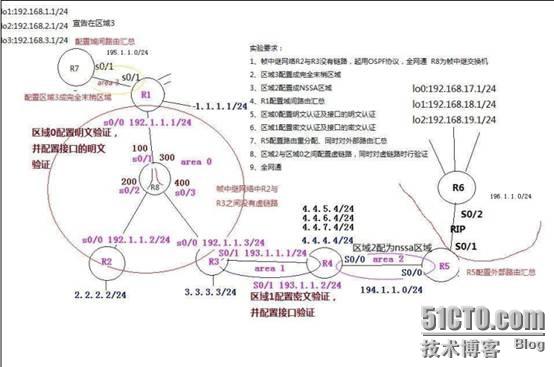
上为Top图
实验要求:
1、帧中继网络r2与r3没有链路,启用ospf协议,全网通 r8为帧中继交换机。
2、区域3配置成完全末梢区域。
3、区域2配置成NSSA区域。
4、r1和r4配置域间路由汇总。
5、区域0配置明文认证及接口的明文认证。
6、区域1配置密文认证及接口的密文认证。
7、r5配置路由重分配、同时对外部路由汇总。
8、区域2与区域0之间配置虚链路,同时对虚链路验证。
9.、全网通。
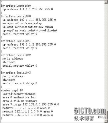
配置命令:R1
enable
config t
host r1
no ip domain look
line console 0
exec-time 0 0
logg syn
int lo0
ip add 1.1.1.1 255.255.255.0
int s 0/0
no shu
encap frame-relay //对接口封装帧中继协议
ip add 192.1.1.1 255.255.255.0
ip ospf network point-to-mu //配置接口ospf协议的网络类型为点到多点
ip ospf authentication-key huayu //对接口配置区域0的明文验证 验证字:huayu
int s 0/1
no shu
ip add 195.1.1.2 255.255.255.0
router ospf 10
network 192.1.1.1 0.0.0.0 area 0
network 1.1.1.1 0.0.0.0 area 0
network 195.1.1.2 0.0.0.0 area 3
area 3 stub no-su //配置区域3为完全末梢区域
area 3 range 192.168.0.0 255.255.0.0 //对区域3做域间汇总
area 0 authentication //配置区域0 的明文验证r2
enable
config t
host r2
no ip domain look
line console 0
exec-time 0 0
logg syn
int lo0
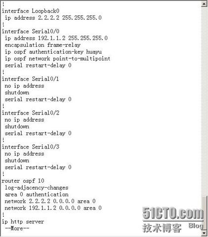
ip add 2.2.2.2 255.255.255.0
int s 0/0
no shu
ip add 192.1.1.2 255.255.255.0
encap frame-relay //对接口封装帧中继协议
ip ospf network point-to-mu //配置接口的ospf协议的网络类型为点到多点
ip ospf authentication-key huayu //配置接口的明文验证 验证字 huayu
router ospf 10
network 192.1.1.2 0.0.0.0 area 0
network 2.2.2.2 0.0.0.0 area 0
area 0 authentication //配置区域0使用明文验证r3
enable
config t
host r3
no ip domain look
line console 0
exec-time 0 0
logg syn
int lo0
ip add 3.3.3.3 255.255.255.0
int s 0/0
no shu
ip add 192.1.1.3 255.255.255.0
encap frame-relay //接口封装帧中继协议
ip ospf network point-to-mu //配置接口ospf协议的网络类型为点到多点
ip ospf authentication-key huayu //配置接口的明文验证 验证字 huayu
int s 0/1
ip add 193.1.1.1 255.255.255.0
ip ospf message-digest-key 10 md5 lifan //配置接口的密文验证 验证字lifan
no shu
router ospf 10
network 192.1.1.3 0.0.0.0 area 0
network 3.3.3.3 0.0.0.0 area 0
network 193.1.1.1 0.0.0.0 area 1
area 1 virtual-link 4.4.7.4 //在区域1配置到路由4.4.7.4的虚链路
area 0 authentication //配置区域0使用明文验证
area 1 authentication message-digest //配置区域1使用密文验证r4
enable
config t
host r4
no ip domain look
line console 0
exec-time 0 0
logg syn
int lo0
ip add 4.4.4.4 255.255.255.0
int lo1
ip add 4.4.5.4 255.255.255.0
int lo2
ip add 4.4.6.4 255.255.255.0
int lo3
ip add 4.4.7.4 255.255.255.0
int s 0/0
no shu
ip add 194.1.1.1 255.255.255.0
int s 0/1
no shu
ip add 193.1.1.2 255.255.255.0
ip ospf message-digest-key 10 md5 lifan //接口配置密文验证 验证字lifan
ip ospf authentication-key huayu //接口配置明文验证 验证字 huayu (因为有到r3的虚链路,所以也要做区域0的验证)
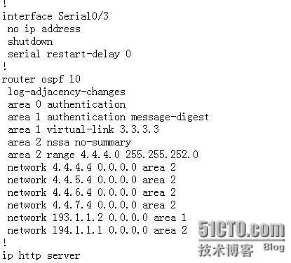
router ospf 10
network 193.1.1.2 0.0.0.0 area 1
network 194.1.1.1 0.0.0.0 area 2
network 4.4.4.4 0.0.0.0 area 2
network 4.4.5.4 0.0.0.0 area 2
network 4.4.6.4 0.0.0.0 area 2
network 4.4.7.4 0.0.0.0 area 2
area 2 nssa no-sum //配置区域2为完全nssa区域
area 1 virtual-link 3.3.3.3 //配置区域1中 到路由3.3.3.3 的虚链路
area 2 range 4.4.4.0 255.255.252.0 //配置区域2的域间汇总
area 1 authentication message-digest //配置区域1 使用密文验证
area 0 authentication //配置区域0使用明文验证(虚链路与区域0相连)r5
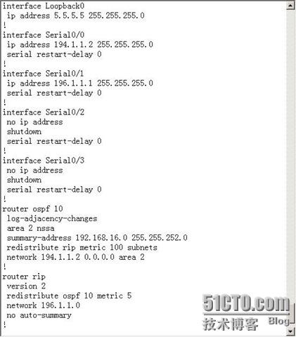
enable
config t
host r5
no ip domain look
line console 0
exec-time 0 0
logg syn
int lo0
ip add 5.5.5.5 255.255.255.0
int s 0/0
no shu
ip add 194.1.1.2 255.255.255.0
int s 0/1
no shu
ip add 196.1.1.1 255.255.255.0
router rip
ver 2 //启用 rip v2
no auto-s //关闭自动汇总
network 196.1.1.0
redistribute ospf 10 metric 5 //路由重分配
router ospf 10
network 194.1.1.2 0.0.0.0 area 2
redistribute rip metric 100 subnets //路由重分配
area 2 nssa //配置区域2为nssa区域
summary-address 192.168.16.0 255.255.252.0 //配置外部路由汇总r6
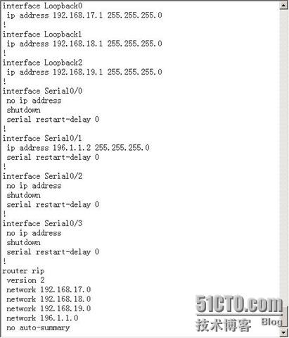
enable
config t
host r6
no ip domain look
line console 0
exec-time 0 0
logg syn
int s 0/1
no shu
ip add 196.1.1.2 255.255.255.0
int lo0
ip add 192.168.17.1 255.255.255.0
int lo1
ip add 192.168.18.1 255.255.255.0
int lo2
ip add 192.168.19.1 255.255.255.0
router rip
ver 2 //启用ripv2
no auto-s //关闭自动汇总
network 196.1.1.0
network 192.168.17.0
network 192.168.18.0
network 192.168.19.0r7
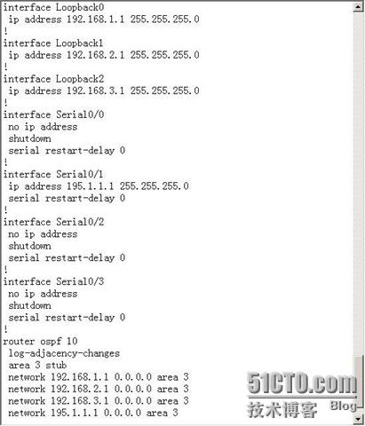
enable
config t
host r7
no ip domain look
line console 0
exec-time 0 0
logg syn
int s 0/1
no shu
ip add 195.1.1.1 255.255.255.0
int lo0
ip add 192.168.1.1 255.255.255.0
int lo1
ip add 192.168.2.1 255.255.255.0
int lo2
ip add 192.168.3.1 255.255.255.0
router ospf 10
network 195.1.1.1 0.0.0.0 area 3
network 192.168.1.1 0.0.0.0 area 3
network 192.168.2.1 0.0.0.0 area 3
network 192.168.3.1 0.0.0.0 area 3
area 3 stub //配置区域3为末梢区域r8
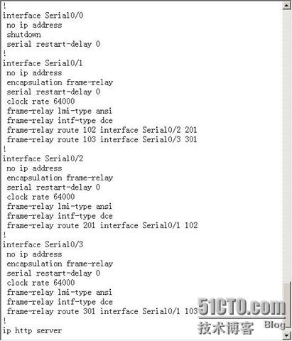
enable
config t
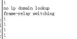
frame-relay switch
host r8
no ip domain look
line console 0
exec-time 0 0
logg syn
int s 0/1
no shu
encap frame-relay //封装帧中继协议
frame-relay lmi-type ansi //配置本地管理接口类型为 ansi
frame-relay intf-type dce //接口类型配置为dce
clock rate 64000 //配置时钟频率
frame-relay route 102 int s 0/2 201 //配置经102到 s0/2的201的虚链路
frame-relay route 103 int s 0/3 301 //配置经103到s0/3的301的虚链路
int s 0/2
no shu
encap frame-relay
frame-relay lmi-type ansi
frame-relay intf-type dce
clock rate 64000
frame-relay route 201 int s 0/1 102
int s 0/3
no shu
encap frame-relay
frame-relay lmi-type ansi
frame-relay intf-type dce
clock rate 64000
frame-relay route 301 int s 0/1 103
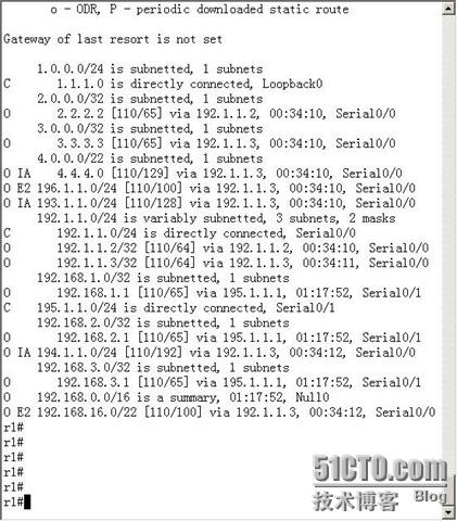
路由配置信息R1
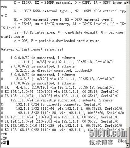
R2
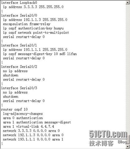
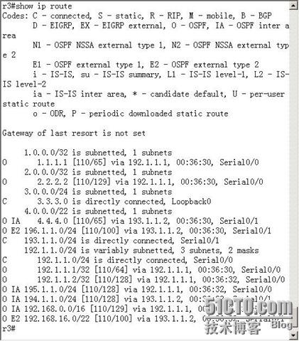
R3
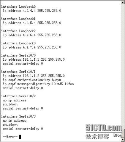
R4
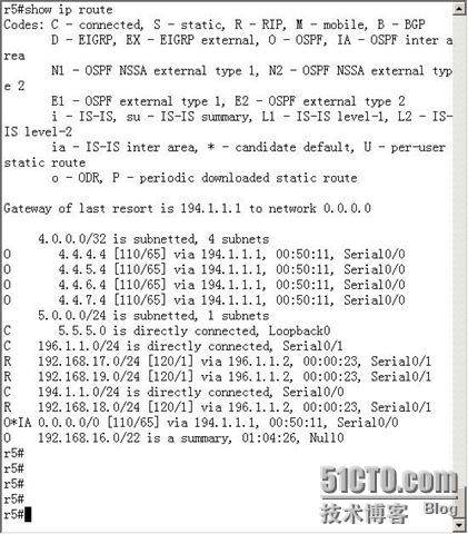
R5
R6

R7
R8
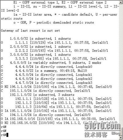
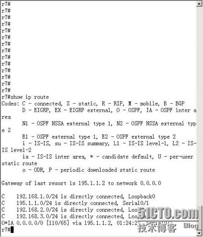
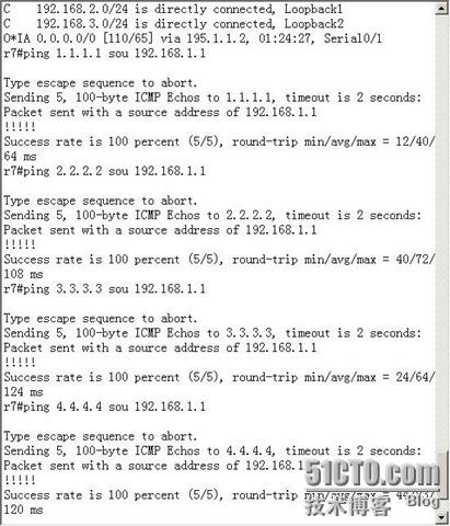
测试
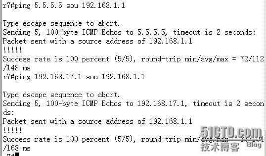
图中ping5.5.5.5 ping通 是因为我后来没ping通5.5.5.5后宣告了 5.5.5.5 ,上面的命令没有宣告5.5.5.5,所以是ping不通的
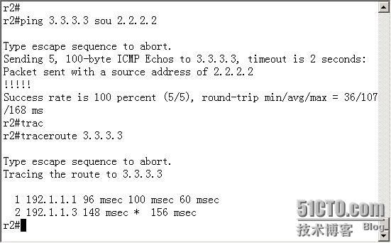
没有r2直接到r3的虚链路, r2经过r1到达r3
全网通

相关文章推荐
- cisco路由器综合实验之 ospf在多域环境下的应用
- ospf综合实验2 2012/9/8
- rip ospf 加密 路由图 综合实验
- OSPF与NAT综合应用实验案例
- OSPF综合实验报告
- 超详细OSPF的基本概念;OSPF多区域配置和综合实验
- RIP和OSPF双点双向重发布_综合实验
- eigrp与ospf的综合实验(还是要想想办法才做得出来哦)
- 路由交换综合实验(用HSRP、OSPF、VTP、DHCP、ACL等)
- OSPF-综合实验
- OSPF及OSPF的CCNA级别的综合实验(8)
- 多区域OSPF综合实验
- cisco路由器综合实验之五 动态路由协议(ospf单域)
- OSPF综合实验--多区域、Stub、NSSA、路由聚合与路由引入
- OSPF 综合实验
- 关于eigrp,ospf,rip的综合实验
- Cisco Packet Tracer 小实验 VLAN、VTP、DHCP、OSPF、NAT综合
- NA-NP-IE系列实验26: 基于链路的OSPF 简单口令认证
- OSPF配置实验(一)
- 实验二 线性表综合实验——间接寻址