Cisco Packet Tracer学习
2010-06-02 20:09
573 查看
实验目的:分配了一个网段,公网IP地址如下:
218.2.135.1/29 ------ 218.2.135.6/29
想用218.2.135.1/29这个IP地址让内部的PC去访问外网,其它的几个IP地址都分配给内部的服务器使用,这三台内部的服务器需 要提供给外网用户访问。
在这里PC1与PC2在VLAN 10里面,PC3和PC4在VLAN 20里面。
1、首先拉好每个元素
如图

2、给PC0增加PT-HOST-NM-1AM

3、在ISP路由上添加WIC-1AM模块

4、PSTN中配置modern4、5的号码
5、在ISP的路由器上面来配置
我们现在来测试一下呢?

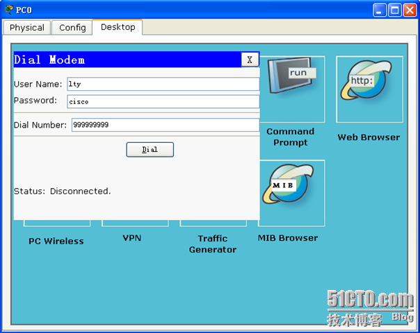
在PC上面我们点击“Dial-up”输入我们刚才在路由器上面配置的用户名及密码,下面“Dial Number”输入我们PSTN分配给我们ISP的那个电话号码。然后点击“Dial”进行拨号。

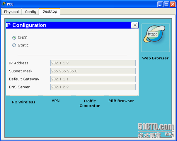
上图就表示我们已经拨号成功了!看见状态显示的是“连接(Connected)”。我们在到“IP Configuration”那里将IP地址的获取方式改成“DHCP”然后看看能够获取我们的IP地址不。

从上图我们可以看见已经通过PSTN在我们的ISP路由器上面获取到了IP地址。这里我们就已经完成了。我们接着在ISP上面将其它的配置完 成。
现在我们的ISP就已经配置完成了。我们来看看DNS服务器的配置,以及WWW服务器的配置。

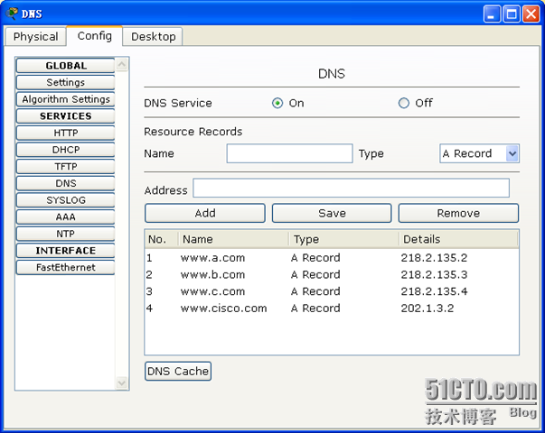
DNS服务器的IP地址。

做了一个我们的域名解析。

这是我们WWW服务器的IP地址,WWW功能默认打开的,我们就不用再去配置了。
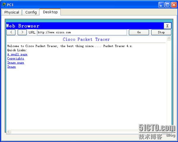
我们现在在我们的PC0上面来测试一下看看能不能够打开我们的WWW服务器。

看看从PC0上面能够通过我们的域名http://www.cisco.com访 问到我们的WWW服务器上面,这说明我们的DNS、WWW、PSTN这些配置都是正确的,现在就剩下我们的企业这边了,我们现在来看看我们企业之边如果配 置呢?
我们现在来看看交换机上面划分两个VLAN,VLAN10和VLAN20。
现在在PC上面来看看能否正常获取我们的IP地址以及能不能访问我们的公网呢?

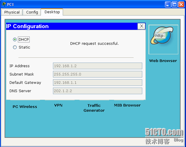
我们可以看到PC1位于VLAN10中,能够获取到我们路由器分配给VLAN10的网段的IP地址。

当它通过DHCP获取到了IP地址以后,能够正常访问我们的公网。我们再来看看VLAN20里面的PC能否正常使用。

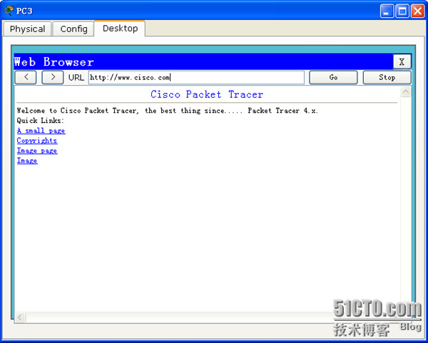
PC3位于VLAN20中,能够通过路由器获取到属于VLAN20网段的IP地址。看看能否正常访问我们的公网呢?

从上图我们可以看见,可以正常访问。
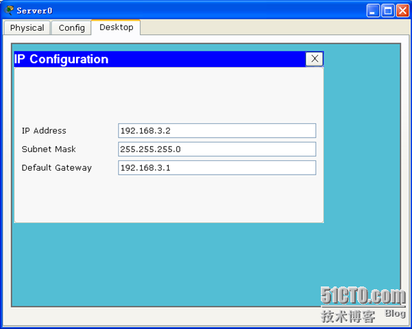
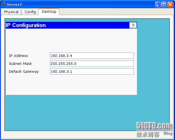
用户这边我们已经解决了访问公网的问题了,我们来看看服务器方面如何做呢?我们先来看看服务器上面的IP地址


我们来看看我们企业内部的路由器上面如何来进行配置如何来做NAT呢?
现在我们到PC0上面来测试看看呢?


好了目前为止,我们的实验到此为止就完了。注意上面这个实验没有考虑安全方面。
218.2.135.1/29 ------ 218.2.135.6/29
想用218.2.135.1/29这个IP地址让内部的PC去访问外网,其它的几个IP地址都分配给内部的服务器使用,这三台内部的服务器需 要提供给外网用户访问。
在这里PC1与PC2在VLAN 10里面,PC3和PC4在VLAN 20里面。
1、首先拉好每个元素
如图
2、给PC0增加PT-HOST-NM-1AM
3、在ISP路由上添加WIC-1AM模块
4、PSTN中配置modern4、5的号码
5、在ISP的路由器上面来配置
ISP(config)#username lty password cisco    这里的用户名密码等一会我们在PC上面拨号使用。
ISP(config)#ip dhcp pool PSTN      当我们拨号成功以后ISP给我们PC自动分配的IP地址就从这个地址池中调用
ISP(dhcp-config)#network 202.1.1.0 255.255.255.0  给我们客户机分配的IP地址
ISP(dhcp-config)#default-ISP 202.1.1.1    给我们客户机分配的默认网关
ISP(dhcp-config)#dns-server 202.1.2.2     给我们客户机指定的DNS
ISP(dhcp-config)#exit
ISP(config)#ip dhcp excluded-address 202.1.1.1    我们要把网关的那个IP地址排除掉
我们现在来测试一下呢?
在PC上面我们点击“Dial-up”输入我们刚才在路由器上面配置的用户名及密码,下面“Dial Number”输入我们PSTN分配给我们ISP的那个电话号码。然后点击“Dial”进行拨号。

上图就表示我们已经拨号成功了!看见状态显示的是“连接(Connected)”。我们在到“IP Configuration”那里将IP地址的获取方式改成“DHCP”然后看看能够获取我们的IP地址不。
从上图我们可以看见已经通过PSTN在我们的ISP路由器上面获取到了IP地址。这里我们就已经完成了。我们接着在ISP上面将其它的配置完 成。
| ISP(config)#int fa0/0 连的我们的DNS服务器 ISP(config-if)#ip add 202.1.2.1 255.255.255.0 ISP(config-if)#no shut ISP(config-if)#exit ISP(config)#int fa0/1 连的我们的WWW服务器 ISP(config-if)#ip add 202.1.3.1 255.255.255.0 ISP(config-if)#no shut ISP(config-if)#exit ISP(config)#int s0/0/0 连的我们公司的路由器 ISP(config-if)#ip add 218.2.135.6 255.255.255.248 ISP(config-if)#clock rate 64000 ISP(config-if)#no shut ISP(config-if)#exit ISP(config)# |

DNS服务器的IP地址。
做了一个我们的域名解析。

这是我们WWW服务器的IP地址,WWW功能默认打开的,我们就不用再去配置了。
我们现在在我们的PC0上面来测试一下看看能不能够打开我们的WWW服务器。

看看从PC0上面能够通过我们的域名http://www.cisco.com访 问到我们的WWW服务器上面,这说明我们的DNS、WWW、PSTN这些配置都是正确的,现在就剩下我们的企业这边了,我们现在来看看我们企业之边如果配 置呢?
| Enterprise(config)#int s0/0/0 Enterprise(config-if)#ip add 218.2.135.1 255.255.255.248 Enterprise(config-if)#no shut Enterprise(config-if)#int fa0/0 Enterprise(config-if)#no shut Enterprise(config-if)#exit 以下这几行是做单臂路由的 Enterprise(config)#int fa0/0.1 Enterprise(config-subif)#encapsulation dot1Q 10 Enterprise(config-subif)#ip add 192.168.1.1 255.255.255.0 Enterprise(config-subif)#exit Enterprise(config)#int fa0/0.2 Enterprise(config-subif)#encapsulation dot1Q 20 Enterprise(config-subif)#ip add 192.168.2.1 255.255.255.0 Enterprise(config-subif)#exit Enterprise(config)#int fa0/1 Enterprise(config-if)#ip add 192.168.3.1 255.255.255.0 Enterprise(config-if)#no shut Enterprise(config-if)#exit 这以下的是自动给两个VLAN 分配IP地址的DHCP功能。 Enterprise(config)#ip dhcp pool VLAN10 Enterprise(dhcp-config)#network 192.168.1.0 255.255.255.0 Enterprise(dhcp-config)#default-router 192.168.1.1 Enterprise(dhcp-config)#dns-server 202.1.2.2 Enterprise(dhcp-config)#exit Enterprise(config)#ip dhcp pool VLAN20 Enterprise(dhcp-config)#network 192.168.2.0 255.255.255.0 Enterprise(dhcp-config)#default-router 192.168.2.1 Enterprise(dhcp-config)#dns-server 202.1.2.2 Enterprise(dhcp-config)#exit Enterprise(config)#ip dhcp excluded-address 192.168.1.1 Enterprise(config)#ip dhcp excluded-address 192.168.2.1 这现面是做PAT,以使我们内部的PC可以正常访问我们的外网。 Enterprise(config)#access-list 1 permit 192.168.1.0 0.0.0.255 Enterprise(config)#access-list 1 permit 192.168.2.0 0.0.0.255 Enterprise(config)#ip nat inside source list 1 interface s0/0/0 overload Enterprise(config)#int s0/0/0 Enterprise(config-if)#ip nat outside Enterprise(config-if)#exit Enterprise(config)#int fa0/0.1 Enterprise(config-subif)#ip nat inside Enterprise(config-subif)#exit Enterprise(config)#int fa0/0.2 Enterprise(config-subif)#ip nat inside Enterprise(config-subif)#exit 我们内网要想访问公网就必须使用一条默认路由出去。否 则就只能访问到我们的ISP路由器那里。 Enterprise(config)#ip route 0.0.0.0 0.0.0.0 s0/0/0 |
| Switch(config)#vlan 10 创建VLAN10 Switch(config-vlan)#exit Switch(config)#vlan 20 创建VLAN20 Switch(config-vlan)#exit Switch(config)#int range fa0/1 - 2 将fa0/1与fa0/2两个端口加入到我们的VLAN10中 Switch(config-if-range)#sw mo acc Switch(config-if-range)#sw acc vlan 10 Switch(config-if-range)#exit Switch(config)#int range fa0/3 - 4 将fa0/3与fa0/4两个端口加入到我们的VLAN20中 Switch(config-if-range)#sw mo acc Switch(config-if-range)#sw acc vlan 20 Switch(config-if-range)#exit Switch(config)#int fa0/24 将我们的fa0/24口接路由器这个端口配置成trunk端口 Switch(config-if)#sw mo trunk Switch(config-if)#exit Switch(config)# |
我们可以看到PC1位于VLAN10中,能够获取到我们路由器分配给VLAN10的网段的IP地址。
当它通过DHCP获取到了IP地址以后,能够正常访问我们的公网。我们再来看看VLAN20里面的PC能否正常使用。

PC3位于VLAN20中,能够通过路由器获取到属于VLAN20网段的IP地址。看看能否正常访问我们的公网呢?
从上图我们可以看见,可以正常访问。
用户这边我们已经解决了访问公网的问题了,我们来看看服务器方面如何做呢?我们先来看看服务器上面的IP地址

我们来看看我们企业内部的路由器上面如何来进行配置如何来做NAT呢?
| Enterprise(config)#ip nat inside source static 192.168.3.3 218.2.135.2 给我们的Server1指定一个公网IP地址218.2.135.2 Enterprise(config)#ip nat inside source static 192.168.3.4 218.2.135.3 给我们的Server2指定一个公网IP地址218.2.135.3 Enterprise(config)#ip nat inside source static 192.168.3.2 218.2.135.4 给我们的Server2指定一个公网IP地址218.2.135.4 Enterprise(config)#int fa0/1 Enterprise(config-if)#ip nat inside |


好了目前为止,我们的实验到此为止就完了。注意上面这个实验没有考虑安全方面。

相关文章推荐
- Cisco Packet Tracer 5 汉化版 | 学习网络配置的学习工具
- 使用Cisco Packet Tracer学习TCP/IP协议
- Cisco Packet Tracer 5 汉化版 | 学习网络配置的学习工具
- 第12章,Cisco Packet Tracer系列之--路由器综合路由配置
- 第12章 路由器综合路由配置(Cisco Packet Tracer5.3我做不行)
- Cisco Packet Tracer的使用(一)
- Cisco Packet Tracer做单臂路由的过程
- 第12章 路由器综合路由配置(Cisco Packet Tracer5.3我做不行)
- cisco packet tracer 5.3 实现邮件服务器
- [笔记]Cisco Packet Tracer配置telnet
- 第2章,Cisco Packet Tracer系列之--交换机的基本配置与管理
- 基于区域的OSPF简单口令认证(cisco packet tracer5.3)
- Cisco Packet Tracer使用方法和路由器基本配置
- 计算机网络之Cisco Packet Tracer模拟器使用
- 用cisco packet tracer配置简单AAA认证
- Cisco Packet Tracer 使用方法
- 基于CiscoPacket Tracer6.0网络协议分析实验第一节
- 使用Cisco Packet Tracer之图解PDUs的使用
- 使用Cisco Packet Tracer之小企业的实际工程案例
- python网络编程中,Cisco packet tracer 中两个交换机和一个路由器的配置