【网络工程师路由篇】——OSPF Stub区域(思科模拟器)
OSPF Stub区域
一、OSPF Stub区域功能介绍:
1、stub区域为OSPF的末节区域,能够过滤掉 4类、5类LSA(这样就不会接收到OSPF域外的路由),能够减小链路状态数据库及路由表。
2、该区域的ABR会为stub区域产生一条域间的O *IA 0/0的默认路由,下发到该区域,保证到OSPF域外的路由可达性
二、OSPF Stub区域应用场景:
在OSPF域的一个末节区域,比如就一台设备,单链路与核心骨干区域连接,这台设备的性能可能还比较低,内存,CPU都比较紧张,另外不论路由条目详细还是宽泛都区别不大,因为这个区域需要访问其他区域,或者是OSPF域外的网段的时候,他的路由的下一跳都是这个单链路所对应的下一跳核心设备的IP,所以这个区域没有必要学习到大量的OSPF外部路由,此时就可以考虑将该区域配置成stub区域,以减轻这个区域的路由条目的压力与计算的资源消耗。
三、OSPF Stub区域实验配置:
注意:
1)stub区域为末节区域,stub区域过滤 4类、5类 LSA,并且在ABR路由器产生一条3类LSA的默认路由
3)stub区域内的路由器不允许引入ospf的域外路由
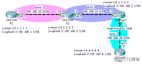
1、拓扑图
2、实验目的:
1)将area 2 配置为stub区域,过滤 4类、5类 LSA
3、配置思路:
1)搭建好拓扑图环境,标出规划好的IP地址
2)修改网络设备默认名称、配置好IP地址
3)配置基础OSPF,使各网段之间实现互访
4)在area 2 配置Stub区域
4、配置过程:
步骤一:修改网络设备默认名称、配置好IP地址
1) 路由器R1做基础接口配置,并修改设备名称
Router>en //进入特权模式
Router#conf t //进入全局配置模式
Enter configuration commands, one per line. End with CNTL/Z.
Router(config)#hostname R1 //给设备改名称
R1(config)#int fa0/1 //进入接口配置模式
R1(config-if)#ip address 192.168.12.1 255.255.255.0 //配置接口的ip地址、子网掩码
R1(config-if)#no shut //激活接口,拓扑图上接口由红变绿
R1(config-if)# //以下两行为激活接口的提示信息
%LINK-5-CHANGED: Interface FastEthernet0/1, changed state to up
%LINEPROTO-5-UPDOWN: Line protocol on Interface FastEthernet0/1, changed state to up
R1(config)#int loopback 0
%LINK-5-CHANGED: Interface Loopback0, changed state to up
R1(config-if)#
%LINEPROTO-5-UPDOWN: Line protocol on Interface Loopback0, changed state to up
R1(config-if)#ip add 192.168.1.1 255.255.255.0
R1(config-if)#no shut
2) 路由器R2做基础接口配置,并修改设备名称
Router(config)#hostname R2
R2(config)#int fa0/1
R2(config-if)#ip add 192.168.12.2 255.255.255.0
R2(config-if)#no shut
%LINK-5-CHANGED: Interface FastEthernet0/1, changed state to up
%LINEPROTO-5-UPDOWN: Line protocol on Interface FastEthernet0/1, changed state to up
R2(config-if)#int fa0/0
R2(config-if)#ip add 192.168.23.1 255.255.255.0
R2(config-if)#no shut
R2(config-if)#exit
R2(config)#int loopback 0
%LINK-5-CHANGED: Interface Loopback0, changed state to up
R2(config-if)#
%LINEPROTO-5-UPDOWN: Line protocol on Interface Loopback0, changed state to up
R2(config-if)#ip add 192.168.2.1 255.255.255.0
R2(config-if)#no shut
3) 路由器R3做基础接口配置,并修改设备名称
R3(config)#int fa0/0
R3(config-if)#ip add 192.168.23.2 255.255.255.0
R3(config-if)#no shut
R3(config-if)#int fa0/1
R3(config-if)#ip add 192.168.34.1 255.255.255.0
R3(config-if)#no shut
R3(config-if)#exit
R3(config)#int loopback 0
R3(config-if)#ip add 192.168.3.1 255.255.255.0
R3(config-if)#no shut
4) 路由器R4做基础接口配置,并修改设备名称
R4(config)#int fa0/1
R4(config-if)#ip add 192.168.34.2 255.255.255.0
R4(config-if)#no shut
R4(config-if)#exit
R4(config)#int loopback 0
R4(config-if)#ip add 192.168.4.1 255.255.255.0
R4(config-if)#no shut
步骤二、配置基础OSPF
1) R1:
R1(config)#router ospf 1 //使能OSPF,并配置进程号为1
R1(config-router)#router-id 1.1.1.1 //配置router-id
R1(config-router)#network 192.168.1.1 0.0.0.0 area 1 //发布网段,并将网段分配进area 1 区域
R1(config-router)#network 192.168.12.0 0.0.0.255 area 1
2) R2:
R2(config)#router ospf 1
R2(config-router)#router-id 2.2.2.2
R2(config-router)#network 192.168.12.0 0.0.0.255 area 1
R2(config-router)#network 192.168.23.0 0.0.0.255 area 0
R2(config-router)#network 192.168.2.1 0.0.0.0 area 0
00:59:28: %OSPF-5-ADJCHG: Process 1, Nbr 1.1.1.1 on FastEthernet0/1 from LOADING to FULL, Loading Done //该信息表明邻居已经建立成功
R2(config-router)#end
3) R3:
R3(config)#router ospf 1
R3(config-router)#router-id 3.3.3.3
R3(config-router)#network 192.168.23.0 0.0.0.255 area 0
R3(config-router)#
00:40:03: %OSPF-5-ADJCHG: Process 1, Nbr 2.2.2.2 on FastEthernet0/0 from LOADING to FULL, Loading Done
R3(config-router)#network 192.168.34.0 0.0.0.255 area 2
R3(config-router)#network 192.168.3.1 0.0.0.0 area 0
4) R4:
R4(config)#router ospf 1
R4(config-router)#router-id 4.4.4.4
R4(config-router)#network 192.168.4.1 0.0.0.0 area 2
R4(config-router)#network 192.168.34.0 0.0.0.255 area 2
R4(config-router)#
01:12:18: %OSPF-5-ADJCHG: Process 1, Nbr 3.3.3.3 on FastEthernet0/1 from LOADING to FULL, Loading Done
步骤三:将area 2 配置为OSPF Stub区域:
注意:
1)配置stub区域,该区域内的所有路由器/交换机都必须配置为stub区域
2)骨干区域(area 0)不能配置为stub区域
R3(config)#router ospf 1
R3(config-router)#area 2 stub ----->area 2 配置为stub区域
01:01:35: %OSPF-5-ADJCHG: Process 1, Nbr 4.4.4.4 on FastEthernet0/1 from FULL to DOWN, Neighbor Down: Adjacency forced to reset
01:01:35: %OSPF-5-ADJCHG: Process 1, Nbr 4.4.4.4 on FastEthernet0/1 from FULL to Down: Interface down or detached
R4(config)#router ospf 1
R4(config-router)#area 2 stub
R4(config-router)#
01:34:09: %OSPF-5-ADJCHG: Process 1, Nbr 3.3.3.3 on FastEthernet0/1 from LOADING to FULL, Loading Done
R4(config-router)#end
四、配置验证
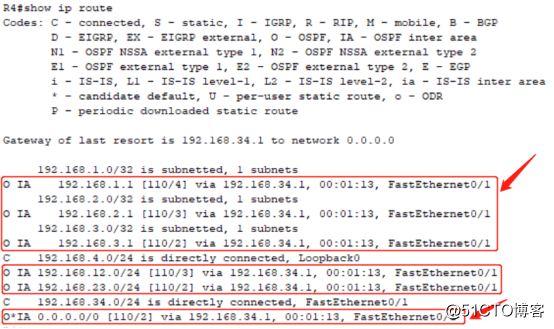
1)查看路由表:查看stub区域路由器的路由,若域外路由被过滤了,区域间路由还在,且产生了一条OIA的默认路由,则stub区域配置正确。 如下图:
2)测试路由器本地环回接口loopback 之间的连通性,如下图:
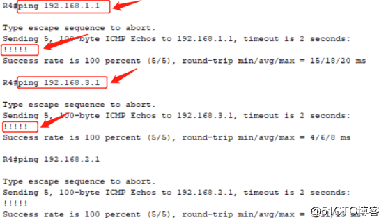
出现如上图的“!!!!!”则说明各IP之间可以实现通信
至此,OSPF Stub区域划分实验完成。
五、总结与扩展:如果需要更多基础实验配置实例,可以加入网工交流群:696283186
OSPF特殊区域包含Stub和Nssa两个区域,两个区域区别如下:
stub区域:过滤掉4、5类lsa,用默认路由代替,精简路由表
nssa区域:过滤掉4,5类,但自身也可以做重发布,引入的外部路由用7类表示
本文内容展示了Stub区域的配置,Nssa区域的配置也可以参考本文配置。

- 【学术报告】阿里巴巴张刚:生成式对抗网络与人脸属性编辑
- 【学术报告】阿里巴巴洪佳鹏:生成对抗网络和隐层属性交换的人脸属性迁移
- 【网络工程师路由篇】——华为静态路由基础
- .NET 云原生架构师训练营(模块二 基础巩固 HTTP管道与中间件)--学习笔记
- TCP:一个悲伤的故事
- 《面试官不讲武德》对Java初级程序猿死命摩擦Http协议
- 基于MARS的移动APP网络通信开发实践
- 网络中最小费用最大流
- Sumap网络测绘探测C&C远控在野情况分析
- 【网络工程师配置篇】——OSPF汇总配置!
- 跟着 GitHub 学习 Restful HTTP API 设计
- 【网络工程师配置篇】——OSPF基础配置!
- 【网络工程师配置篇】——华为RIP路由基础配置!
- 小于500人且有vlan划分、分层和使用路由协议的网络设计与配置
- 【网络工程师精华篇】华为路由交换机基础命令!
- 使用shodan入/侵网络摄像头实战(无需使用kali)
- 用牛郎织女来解释Https
- 假装网络工程师26——MPLS跨AS通信optionB
- 传输层-Transport Layer(下):UDP与TCP报头解析、TCP滑动窗口、TCP拥塞控制详解
- TCP连接时动态端口的相关问题说明