C# 制作 仪表
2015-10-30 12:57
387 查看
以前在百度写的文档,转移到此处
前些天在做NetAnalyzer时,需要使用一个指针仪表,网上看了一下,也有人做过,但是大部分都是收费的,本着自力更生的原则,于是决定自己设计一个,今天拿出来有读者分享一下。
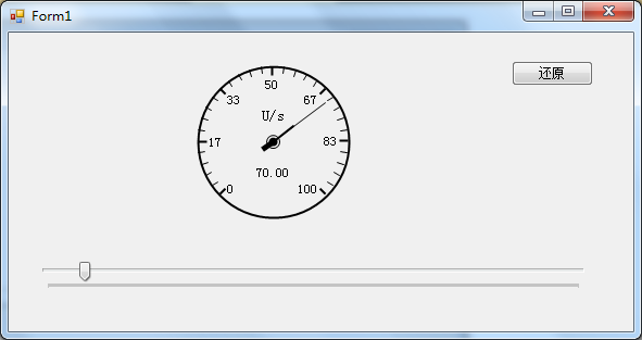
首先是截图:

该仪表是以控件形式提供
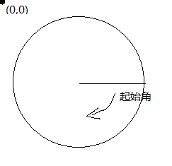
在开始之前还要赘述一点关于GDI+中角度的计算
如下图

在WinForm中左上角的点位(0,0),即原点,而其起始角则是图中划线处开始的,即为 rad=0;
在绘图时,尤其是做过扇形统计图的人应该比较清楚。
--------------------------------------------------------
接下来就是正式开始
首先新建控件,设置为witdth=height=150 ,可以自己定义,我在这里时可以自适应的
将背景颜色设置为Transparent(透明色),方便以后使用时减少干扰
在该仪表中主要分为两部分:背景部分(外框,刻度,单位等一些列基本不需要频繁变化的部分),前景部分(指针部分)
所以为了不是两个图层不相互影响,我们将背景绘制在控件的BackgroundImage 属性上,而指针部分则需要一个pictrueBox控件作为载体。
首先画背景
在绘制背景时,又分为外框、刻度,指针固定中心等
前些天在做NetAnalyzer时,需要使用一个指针仪表,网上看了一下,也有人做过,但是大部分都是收费的,本着自力更生的原则,于是决定自己设计一个,今天拿出来有读者分享一下。
首先是截图:

该仪表是以控件形式提供
在开始之前还要赘述一点关于GDI+中角度的计算
如下图

在WinForm中左上角的点位(0,0),即原点,而其起始角则是图中划线处开始的,即为 rad=0;
在绘图时,尤其是做过扇形统计图的人应该比较清楚。
--------------------------------------------------------
接下来就是正式开始
首先新建控件,设置为witdth=height=150 ,可以自己定义,我在这里时可以自适应的
将背景颜色设置为Transparent(透明色),方便以后使用时减少干扰
在该仪表中主要分为两部分:背景部分(外框,刻度,单位等一些列基本不需要频繁变化的部分),前景部分(指针部分)
所以为了不是两个图层不相互影响,我们将背景绘制在控件的BackgroundImage 属性上,而指针部分则需要一个pictrueBox控件作为载体。
首先画背景
在绘制背景时,又分为外框、刻度,指针固定中心等
// 绘制背景 用来总体控制背景的绘制
private void DrawBackImg()
{
Bitmap bit = new Bitmap(this.Width, this.Height);
Graphics gp = Graphics.FromImage(bit);
gp.SmoothingMode = System.Drawing.Drawing2D.SmoothingMode.HighQuality;
#region 在这里可以扩展需要绘制的背景项目
//外框
drawFrame(gp);
// 画刻度
DrawRuling(gp);
//画点
drawPoint(gp);

//绘制单位

DrawUnitStr(gp);

#endregion

//当绘制完成后,直接直接设置为背景

this.BackgroundImage = bit;
}

//绘制单位

private void DrawUnitStr(Graphics gp)
{
int cer = _diameter / 2;
gp.DrawString(_unitStr, new Font("宋体", 10), new SolidBrush(_frameColor), new PointF(cer, (float)(cer - cer * 0.3)), strFormat);

}

/// <summary>
/// 画外框
/// </summary>
/// <param name="gp"></param>
private void drawFrame(Graphics gp)
{
Pen pen = new Pen(_frameColor, 2);
Rectangle rec = new Rectangle(5, 5, _diameter - 10, _diameter - 10);
gp.DrawEllipse(pen, rec);
}
// 画刻度  此次较为复杂,主要是在绘制刻度值时需要处理
private void DrawRuling(Graphics gp)
{
//刻度
int cerX = _diameter / 2;
int cerY = _diameter / 2;

//这里需要注意,因外在上面的图中标识了rad=0的位置,而我们的仪表时270度的,0点在135度处,

//为了符合该效果所以起始位置设为135度。
float start = 135;
float sweepShot = 0;
int dx = 0;
int dy = 0;
int soildLenght = 8;
Pen linePen = new Pen(_frameColor, 1);
float span = (float)(_maxValue / 30);
float sp = 0;
//用于右边数字右对齐
StringFormat stf = new StringFormat();
stf.Alignment = StringAlignment.Far;

StringFormat stfMid = new StringFormat();
stfMid.Alignment = StringAlignment.Center;
stfMid.LineAlignment = StringAlignment.Center;
for (int i = 0; i <= 30; i++)
{
//注意此处,C#提供的三角函数计算中使用的弧度值,而此处获取的是角度值,需要转化

double rad = (sweepShot + start) * Math.PI / 180;
float radius = _diameter / 2 - 5;
int px = (int)(cerX + radius * Math.Cos(rad));
int py = (int)(cerY + radius * Math.Sin(rad));
if (sweepShot % 15 == 0)
{
linePen.Width = 2;

//计算刻度中的粗线
dx = (int)(cerX + (radius - soildLenght) * Math.Cos(rad));
dy = (int)(cerY + (radius - soildLenght) * Math.Sin(rad));

//绘制刻度值,注意字串对其方式
string str = sp.ToString("f0");
if (sweepShot <= 45)
{
gp.DrawString(str, new Font("宋体", 9), new SolidBrush(_frameColor), new PointF(dx, dy - 5));
}
else if (sweepShot > 45 && sweepShot < 135)
{
gp.DrawString(str, new Font("宋体", 9), new SolidBrush(_frameColor), new PointF(dx, dy));
}
else if (sweepShot == 135)
{
gp.DrawString(str, new Font("宋体", 9), new SolidBrush(_frameColor), new PointF(dx, dy + 10), stfMid);
}
else if (sweepShot > 135 && sweepShot < 225)
{
gp.DrawString(str, new Font("宋体", 9), new SolidBrush(_frameColor), new PointF(dx, dy), stf);
}
else if (sweepShot >= 225)
{
gp.DrawString(str, new Font("宋体", 9), new SolidBrush(_frameColor), new PointF(dx, dy - 5), stf);
}

}
else
{

//计算刻度中细线

linePen.Width = 1;
dx = (int)(cerX + (radius - soildLenght + 2) * Math.Cos(rad));
dy = (int)(cerY + (radius - soildLenght + 2) * Math.Sin(rad));
}

//绘制刻度线
gp.DrawLine(linePen, new Point(px, py), new Point(dx, dy));
sp += span;
sweepShot += 9;
}
}
//画中间的点
private void drawPoint(Graphics gp)
{
Pen p = new Pen(_frameColor);
int tmpWidth = 6;
int px = _diameter / 2 - tmpWidth;

gp.DrawEllipse(p, new Rectangle(px, px, 2 * tmpWidth, 2 * tmpWidth));

//在画点时,我使用了指针的颜色,这样看起来,更真实一点
gp.FillEllipse(new SolidBrush(_pinColor), new Rectangle(px + 2, px + 2, 2 * tmpWidth - 4, 2 * tmpWidth - 4));
}

-------------------------------------------

画指针

绘制指正时,最大的问题就是界面闪速,除了在控件构造方法里添加如下代码:

SetStyle(ControlStyles.OptimizedDoubleBuffer | ControlStyles.ResizeRedraw | ControlStyles.AllPaintingInWmPaint, true);
UpdateStyles();

绘制方式也需要调整,方法如下:

//为了方式绘制指针时产生的闪烁,PictureBox添加该事件方法

private void pic_Paint(object sender, PaintEventArgs e)
{
DrawForeImg(e.Graphics);
}

//使用方法

public double ChangeValue
{
get { return _changeValue; }
set
{
if (value <= _maxValue)
_changeValue = value;
else
{
//完成自适应性
MaxValue = value;
_changeValue = value;
}
//通过该方法,可以使指针自动绘制(其实就是强制重绘)

pic.Invalidate();
}
}

//指针的具体画法

private void DrawForeImg(Graphics gp)
{
Bitmap bit = new Bitmap(this.Width, this.Height);
Graphics g = Graphics.FromImage(bit);
g.SmoothingMode = System.Drawing.Drawing2D.SmoothingMode.HighQuality;

//画针
DrawPin(g);
DrawString(g);

//注意此处的绘制方式,这样可以有效减少界面的闪烁问题。
gp.DrawImage(bit, new Point(0, 0));
g.Dispose();

}
//画针
private void DrawPin(Graphics g)
{
int cer = _diameter / 2;
float start = 135;
float sweepShot = (float)(_changeValue / _maxValue * 270);

Pen linePen = new Pen(_pinColor, 1);
Pen NxPen = new Pen(_pinColor, 2);
Pen xPen = new Pen(_pinColor, 5);
double rad = (sweepShot + start) * Math.PI / 180;
float radius = _diameter / 2 - 5;
int dx = (int)(cer + (_PinLen) * Math.Cos(rad));
int dy = (int)(cer + (_PinLen) * Math.Sin(rad));

int px = (int)(cer + (_PinLen * 0.4) * Math.Cos(rad));
int py = (int)(cer + (_PinLen * 0.4) * Math.Sin(rad));

int nx = (int)(cer - (NxPinLen) * Math.Sin(rad));
int ny = (int)(cer - (NxPinLen) * Math.Cos(rad));
g.DrawLine(linePen, new Point(cer, cer), new Point(dx, dy));
g.DrawLine(NxPen, new Point(cer, cer), new Point(px, py));
g.DrawLine(xPen, new Point(cer, cer), new Point(ny, nx));
}

//绘制在仪表下面的值

private void DrawString(Graphics g)
{
int cer = _diameter / 2;
string str = _changeValue.ToString("F2");
g.DrawString(str, new Font("宋体", 9), new SolidBrush(_pinColor), new PointF(cer, (float)(cer + cer * 0.4)), strFormat);
}
相关文章推荐
- C#使用自定义字体(从文件获取)
- C#序列化
- superGridControl控件中显示图片功能实现
- c#——表达式树在LINQ动态查询
- BarCode Reader SDK使用教程:如何解PDF147码
- C# Dictionary 的几种遍历方法<转>
- C# DataTable中执行DataTable.Select("条件") <转>
- C#如何读写和创建INI文件
- C#判断文字是否为汉字
- 《C#编程风格》还记得多少
- C# 哈希表
- c#——ExpessionTree(表达式树)
- C# 函数式编程
- C# List<T>的详细用法
- 【Bug】c#使用oleDB读excel读取不到最后一列,把Excel表格打开随便改动一列的格式就能读取出来了。请问这是什么问题
- C# ADO.NET中的五个主要对象<转>
- C# integrated security=SSPI<转>
- 窗口传值方法(socket多窗口共用)
- C# 共享文件读取(转)
- C# .NET 页面间传值的几种方法<转>
