LinuxCNC+EtherCAT(6)之LinuxCNC使用,翻译
2015-10-24 22:23
681 查看
来自https://www.buildyourcnc.com/item/control-SOFTWARE-linuxcnc
Introduction:
If you have Linux, or want to use a Linux based CNC control software, EMC2 is a great option. EMC2 is a very powerful and full featured CNC control software that features a large viewing are,
simple configuration and control panel.
Description:
The download option recommended is the .iso. A .iso is a file that can be run from the computer startup, like a windows installation disk. The .iso will require a special method to burn to a CD
or DVD . Se instructions to get this done.
Instructions
Once you download the .iso, this file will need to be burned to a CD or DVD. If a CD is used, the CD must have 700 MB capacity.
1
To burn the file to a CD/DVD in Windows, use a program like http://infrarecorder.org/ which
is free to use. Insert the CD/DVD into the drive (burner) and start Infra Recorder. Select Action -> Burn Image and select the .iso that was downloaded.
Once the .iso file is burned to the CD/DVD, you can use it to install Ubuntu with EMC2 already installed. The CD/DVD can also be used as a Live CD to try the software before you install it on
the computer. Simply install the software following the menu selections given when you boot the computer with the CD/DVD in the drive. If the computer does not boot on the CD/DVD, make sure that your bios (a program that the computer runs at startup and is
usually invoked by pressing the del key, or the F2 key depending on the motherboard you are using) is configured so that the CD/DVD drive is selected to have priority in the boot up process.
If you want to install the Ubuntu/EMC2 on a computer that already has Windows installed, the installation process will create a new partition on the hard drive. Precautions should be made, like
backing up your computer before installing Ubuntu and partitioning the hard drive.
2

Once Ubuntu is installed, you will be presented with a desktop. On the top of desktop, there is a taskbar with a menu labeled Applications, Places and System. Application contain specific software
that you install. Places contain a list of main locations and folders on the computer. System contains menus for configuration and setup for the operating system.
3
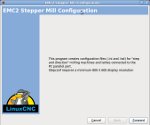
If you click on the Application menu, you will notice that there is a CNC sub menu. This is Linux CNC (EMC2) installation that is included in this integrated Ubuntu .iso package. To setup EMC2
to work correctly with your CNC machine, you will need to select the EMC2 Stepconf Wizard. The image shows the start screen for the Stepconf Wizard.
4
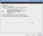
If this is the first time you are creating a configuration for the machine, you will want to use the default "Create a new configuration". You can make as many configurations as you wish. If you
have an existing configuration, then you can choose "Modify a configuration al..." and then select the .stepconf file that you wish to modify.
The Create desktop shortcut and desktop launcher should be checked. This will provide a couple of icons on your desktop to start the EMC2 with the configuration and to open a folder of the configuration
files.
5
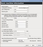
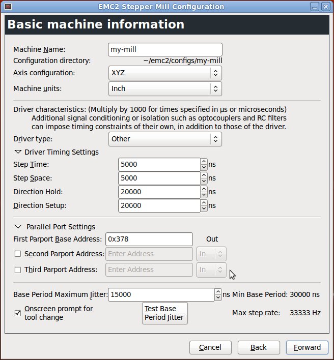
The next screen of the stepconf wizard relates to the basic machine information. This is where you will configure the number of axes you will have on the machine, the units that you wish to use
(inch/mm), the driver type, the parallel port address and the mase period max jitter.
If the parallel port is integrated on your motherboard, the address will most likely be 0x378. The driver settings should be the same as the image. For 3 axis system, the axis configuration should
be XYZ, otherwise select the appropriate configuration from the drop down list.
6
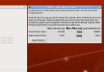
At the bottom of the basic machine information screen is a tool that will attempt to determine the worst case performance scenario for your computer so the machine can be controlled satisfactorily.
By clicking the Test Base Period Jitter, you will see the screen shown here which shows you the Servo thread and the Base thread. The default of 15000 is a very high jitter maximum and should be fine, but if the jitter shows a maximum higher than 15000 in
the test, use that jitter. While testing, perform a few intensive actions like moving windows around and trying a few processes. When you are satisfied that you have taxed the computer, record the max jitter and use that number for the previous screen.
7
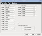
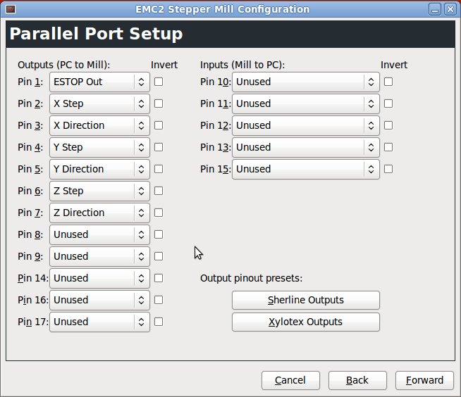
The parallel port setup screen is where you will provide the functions for each pin of the parallel port. You will need two pins for each motor driver (step and direction). So, each axis will
require a step and direction since there is typically a motor driver for each axis. The image shows the basic recommended pin functions. If the step and direction is wired to the - step and - direction (or -CP and -CW) terminals and the other positive terminals
is connected to a common 5v, then you will need to check the "invert" for each step pin that is wired this way. Otherwise, if the common is GND and the step/direction pins are connected to the positive terminals, leave the step invert unchecked. Invert the
direction pin only if the axis is not moving in the desired direction.
Other functions related to spindle, coolant, mist, or other devices that will need to be controlled can be assigned to the remaining pins.
8
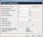
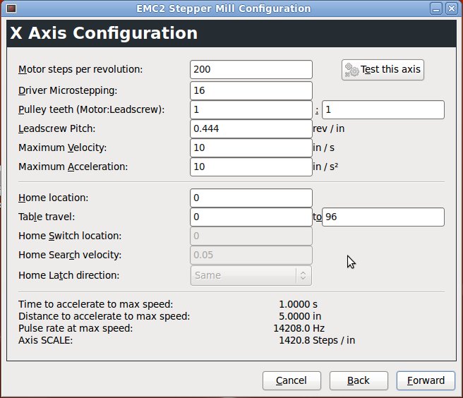
The following screens relate to the configuration for each axis in detail. This screen shows the configuration for the X axis. The parameters on this screen helps is achieving the correct steps
per inch (resolution) for that axis.
Motor steps per revolution is the basic number of steps that the motor will turn with one revolution. If the motor is rated at 1.8 degrees per step, then 200 is the correct number. The datasheet
for your motor should contain the information needed for this value.
The driver microstepping must reflect the setting on the driver for that axis. The microstepping is the number of steps that the drivers will control the motor between a single motor step. The
example on the image is set at 16 microsteps. The end steps per revolution considering the microstepping in this case would be 200 x 16 = 3200.
In most circumstances I find it easier to leave the pulley teeth parameters as 1:1 and modify the leadscrew pitch., even for sprockets and pulleys. For example, if I use a sprocket that has 9
teeth and 1/4 inch pitch, the axis will move 9 x .25 inches = 2.25 inches and take the reciprocal of that number (1/2.25 inches = .44444), or 1 revolution / 2.25 inches.
The velocity values can range depending on the mechanical parts involved. For sprockets, pulleys and rack and pinion, the velocity can be a relatively high number, like 10 inches/second which
is 600 inches/minute. Each second, the end effector will travel 100 inches in one second, which will travel 60 times more in one minute.
Play with the acceleration to get the best possible performance. The higher is better, but start with a number like 10 inches/second/second.
Home location and table travel pertain to the maximum travel and where you intend to home the machine. If the home is at the midpoint of the axis and the axis full travel is 8 feet (96 inches),
then the table travel would be -48 to 48.
Verify the steps at the bottom are correct according to the following formula:
Steps/inch = (motor steps per revolution x microstepping) / lengh of travel per turn
Example:
Step/inch
= (200 steps x 16) / (9 teeth x .25 inches)
= (3200 steps) / (2.25 inches)
= 1422.22222
You might be wondering why this number is not exactly the same as the image. This is because the .444 is a repeating number and the more 4s you add, the closer to 1422.2222 you will get.
9
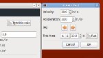
Take a moment to test the axis. You can press the "Test this axis" button on the axis configuration screen to test if the axis works, determine the velocity and acceleration. The jog buttons are
the buttons you will press to move the axis and determine its proper function.
10
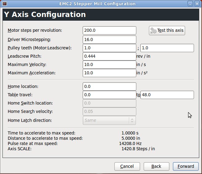
The Y axis configuration in this example is the same as the x-axis configuration since the same drive mechanicals are used for this axis, but if you have different mechanical parts on this axis,
assign the parameters the appropriate values.
11
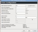
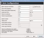
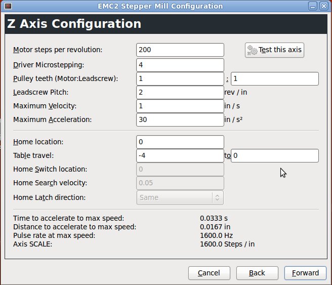
In the z-axis configuration example, a lead screw used as the mechanics. Since the lead screw does not travel very far per revolution (depending on the lead screw), the final resolution can get
very high in relation to the microstepping. In most cases, keep the resolution as low as possible as per your requirements to enable the best torque for the motor.
The lead screw applied in this example has 10 TPI (threads per inch) with 5 starts (5 individual helical threads). The number of turns per inch for this is equal to 10 TPI / 5 starts = 2 effective
turns per inch (not TPI). This is the value required for leadscrew pitch.
12
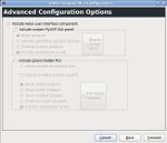
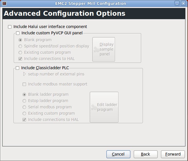
The advanced configuration options does not need to be set unless you wish to have custom GUI (graphical user interface) panels added to the default panels within EMC2. You can add various panels
to enhance EMC2 functions and use devices connected to the machine specifically. One example is the use of a camera for the machine, for whatever purpose. The camera viewer can be made into a panel and opened when the EMC2 "Axis" program is executed.
13
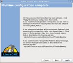
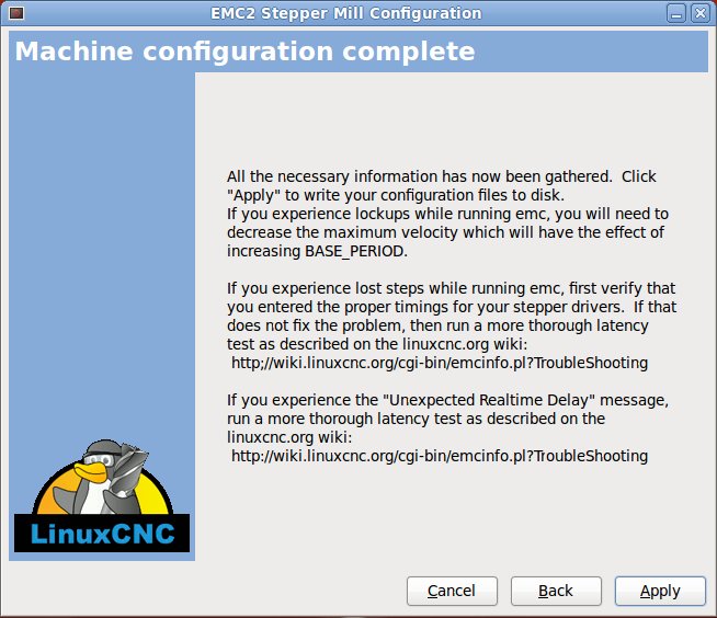
The final screen of the stepconf wizard is the machine configuration complete screen. It's not too late to make any last minute changes, but if you apply and leave the wizard, just go back to
the start of this process and select the "modify a configuration already created with this program".
Clicking apply will create all of the configuration files and the startup icons on the desktop (if that is the selection that you chose in the beginning).
14
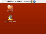
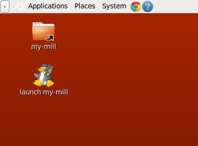
Here is an example of the icons that will be automatically created through the stepconf wizard. The my-mill folder shortcut will open a folder that contains all of the configuration files. These
files are text based and can be edited, but it is best to use the stepconf wizard to modify parameters if you are unfamiliar with editing and understanding the options in the text files.
The icon named "launch my-mill" will start EMC2's "Axis" program and apply the "my-mill" configuration in this instance of "Axis". As stated previously, you can have as many configurations as
you desire and they will have their own launch icon.
15
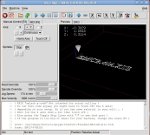
This is an image of the actual Axis porgram running. Briefly, the user interface has these features:
- The view (preview) of the tool paths and where the end effector is located.
- The DRO tab (digital read out) of each axis. This is the location of the end effector in space according to the Cartesian coordinate system.
- Manual controls allow you to control each axis independently, start/stop the spindle, or whatever you have connected to that pin, home the axis or do an axis touch off. Additionally, the speeds
of the end effector or spindle rotation can be modified.
- The bottom portion is reserved for the view of the g-code (the instruction that move the machine).
- The top quick icons has the on/off switch for the machine, play/pause/stop the g-code instruction execution, and change the view states.
To load a g-code file, as with most programs, go to File -> open.
Introduction:
If you have Linux, or want to use a Linux based CNC control software, EMC2 is a great option. EMC2 is a very powerful and full featured CNC control software that features a large viewing are,
simple configuration and control panel.
Description:
The download option recommended is the .iso. A .iso is a file that can be run from the computer startup, like a windows installation disk. The .iso will require a special method to burn to a CD
or DVD . Se instructions to get this done.
Instructions
Once you download the .iso, this file will need to be burned to a CD or DVD. If a CD is used, the CD must have 700 MB capacity.
1
To burn the file to a CD/DVD in Windows, use a program like http://infrarecorder.org/ which
is free to use. Insert the CD/DVD into the drive (burner) and start Infra Recorder. Select Action -> Burn Image and select the .iso that was downloaded.
Once the .iso file is burned to the CD/DVD, you can use it to install Ubuntu with EMC2 already installed. The CD/DVD can also be used as a Live CD to try the software before you install it on
the computer. Simply install the software following the menu selections given when you boot the computer with the CD/DVD in the drive. If the computer does not boot on the CD/DVD, make sure that your bios (a program that the computer runs at startup and is
usually invoked by pressing the del key, or the F2 key depending on the motherboard you are using) is configured so that the CD/DVD drive is selected to have priority in the boot up process.
If you want to install the Ubuntu/EMC2 on a computer that already has Windows installed, the installation process will create a new partition on the hard drive. Precautions should be made, like
backing up your computer before installing Ubuntu and partitioning the hard drive.
2

Once Ubuntu is installed, you will be presented with a desktop. On the top of desktop, there is a taskbar with a menu labeled Applications, Places and System. Application contain specific software
that you install. Places contain a list of main locations and folders on the computer. System contains menus for configuration and setup for the operating system.
3

If you click on the Application menu, you will notice that there is a CNC sub menu. This is Linux CNC (EMC2) installation that is included in this integrated Ubuntu .iso package. To setup EMC2
to work correctly with your CNC machine, you will need to select the EMC2 Stepconf Wizard. The image shows the start screen for the Stepconf Wizard.
4

If this is the first time you are creating a configuration for the machine, you will want to use the default "Create a new configuration". You can make as many configurations as you wish. If you
have an existing configuration, then you can choose "Modify a configuration al..." and then select the .stepconf file that you wish to modify.
The Create desktop shortcut and desktop launcher should be checked. This will provide a couple of icons on your desktop to start the EMC2 with the configuration and to open a folder of the configuration
files.
5
The next screen of the stepconf wizard relates to the basic machine information. This is where you will configure the number of axes you will have on the machine, the units that you wish to use
(inch/mm), the driver type, the parallel port address and the mase period max jitter.
If the parallel port is integrated on your motherboard, the address will most likely be 0x378. The driver settings should be the same as the image. For 3 axis system, the axis configuration should
be XYZ, otherwise select the appropriate configuration from the drop down list.
6

At the bottom of the basic machine information screen is a tool that will attempt to determine the worst case performance scenario for your computer so the machine can be controlled satisfactorily.
By clicking the Test Base Period Jitter, you will see the screen shown here which shows you the Servo thread and the Base thread. The default of 15000 is a very high jitter maximum and should be fine, but if the jitter shows a maximum higher than 15000 in
the test, use that jitter. While testing, perform a few intensive actions like moving windows around and trying a few processes. When you are satisfied that you have taxed the computer, record the max jitter and use that number for the previous screen.
7
The parallel port setup screen is where you will provide the functions for each pin of the parallel port. You will need two pins for each motor driver (step and direction). So, each axis will
require a step and direction since there is typically a motor driver for each axis. The image shows the basic recommended pin functions. If the step and direction is wired to the - step and - direction (or -CP and -CW) terminals and the other positive terminals
is connected to a common 5v, then you will need to check the "invert" for each step pin that is wired this way. Otherwise, if the common is GND and the step/direction pins are connected to the positive terminals, leave the step invert unchecked. Invert the
direction pin only if the axis is not moving in the desired direction.
Other functions related to spindle, coolant, mist, or other devices that will need to be controlled can be assigned to the remaining pins.
8
The following screens relate to the configuration for each axis in detail. This screen shows the configuration for the X axis. The parameters on this screen helps is achieving the correct steps
per inch (resolution) for that axis.
Motor steps per revolution is the basic number of steps that the motor will turn with one revolution. If the motor is rated at 1.8 degrees per step, then 200 is the correct number. The datasheet
for your motor should contain the information needed for this value.
The driver microstepping must reflect the setting on the driver for that axis. The microstepping is the number of steps that the drivers will control the motor between a single motor step. The
example on the image is set at 16 microsteps. The end steps per revolution considering the microstepping in this case would be 200 x 16 = 3200.
In most circumstances I find it easier to leave the pulley teeth parameters as 1:1 and modify the leadscrew pitch., even for sprockets and pulleys. For example, if I use a sprocket that has 9
teeth and 1/4 inch pitch, the axis will move 9 x .25 inches = 2.25 inches and take the reciprocal of that number (1/2.25 inches = .44444), or 1 revolution / 2.25 inches.
The velocity values can range depending on the mechanical parts involved. For sprockets, pulleys and rack and pinion, the velocity can be a relatively high number, like 10 inches/second which
is 600 inches/minute. Each second, the end effector will travel 100 inches in one second, which will travel 60 times more in one minute.
Play with the acceleration to get the best possible performance. The higher is better, but start with a number like 10 inches/second/second.
Home location and table travel pertain to the maximum travel and where you intend to home the machine. If the home is at the midpoint of the axis and the axis full travel is 8 feet (96 inches),
then the table travel would be -48 to 48.
Verify the steps at the bottom are correct according to the following formula:
Steps/inch = (motor steps per revolution x microstepping) / lengh of travel per turn
Example:
Step/inch
= (200 steps x 16) / (9 teeth x .25 inches)
= (3200 steps) / (2.25 inches)
= 1422.22222
You might be wondering why this number is not exactly the same as the image. This is because the .444 is a repeating number and the more 4s you add, the closer to 1422.2222 you will get.
9

Take a moment to test the axis. You can press the "Test this axis" button on the axis configuration screen to test if the axis works, determine the velocity and acceleration. The jog buttons are
the buttons you will press to move the axis and determine its proper function.
10
The Y axis configuration in this example is the same as the x-axis configuration since the same drive mechanicals are used for this axis, but if you have different mechanical parts on this axis,
assign the parameters the appropriate values.
11
In the z-axis configuration example, a lead screw used as the mechanics. Since the lead screw does not travel very far per revolution (depending on the lead screw), the final resolution can get
very high in relation to the microstepping. In most cases, keep the resolution as low as possible as per your requirements to enable the best torque for the motor.
The lead screw applied in this example has 10 TPI (threads per inch) with 5 starts (5 individual helical threads). The number of turns per inch for this is equal to 10 TPI / 5 starts = 2 effective
turns per inch (not TPI). This is the value required for leadscrew pitch.
12
The advanced configuration options does not need to be set unless you wish to have custom GUI (graphical user interface) panels added to the default panels within EMC2. You can add various panels
to enhance EMC2 functions and use devices connected to the machine specifically. One example is the use of a camera for the machine, for whatever purpose. The camera viewer can be made into a panel and opened when the EMC2 "Axis" program is executed.
13
The final screen of the stepconf wizard is the machine configuration complete screen. It's not too late to make any last minute changes, but if you apply and leave the wizard, just go back to
the start of this process and select the "modify a configuration already created with this program".
Clicking apply will create all of the configuration files and the startup icons on the desktop (if that is the selection that you chose in the beginning).
14
Here is an example of the icons that will be automatically created through the stepconf wizard. The my-mill folder shortcut will open a folder that contains all of the configuration files. These
files are text based and can be edited, but it is best to use the stepconf wizard to modify parameters if you are unfamiliar with editing and understanding the options in the text files.
The icon named "launch my-mill" will start EMC2's "Axis" program and apply the "my-mill" configuration in this instance of "Axis". As stated previously, you can have as many configurations as
you desire and they will have their own launch icon.
15

This is an image of the actual Axis porgram running. Briefly, the user interface has these features:
- The view (preview) of the tool paths and where the end effector is located.
- The DRO tab (digital read out) of each axis. This is the location of the end effector in space according to the Cartesian coordinate system.
- Manual controls allow you to control each axis independently, start/stop the spindle, or whatever you have connected to that pin, home the axis or do an axis touch off. Additionally, the speeds
of the end effector or spindle rotation can be modified.
- The bottom portion is reserved for the view of the g-code (the instruction that move the machine).
- The top quick icons has the on/off switch for the machine, play/pause/stop the g-code instruction execution, and change the view states.
To load a g-code file, as with most programs, go to File -> open.

相关文章推荐
- LinuxCNC+EtherCAT(5)之关于LinuxCNC和EMC
- Linux管道基础知识
- Linux top
- 十大好用的Linux实用工具推荐
- 安全参透之旅第1章 KALI LINUX安装
- Linux登陆图形,佛祖保佑
- windows 远程登录Linux
- 中国Linux开源镜像站大全
- Linux命令--uptime
- windows与linux文件格式的互转
- 第 四 十 天:关 于 正 则 的 一 些 小 用 法
- Linux命令--finger
- Linux 内核日志——dmesg
- 1.linux运维之rhel7系统安装(详细步骤)
- Linux命令--dirname
- centos下yum升级内核
- Linux教程:SSH免密码登录的方法
- linux常用命令二之权限,搜索与帮助命令
- linux常用命令一之文件处理命令
- 关 于 正 则 表 达 式 的 类 习 题