华为广域网帧中继(背靠背)配置
2014-07-06 12:56
78 查看
帧中继(背靠背)配置学习目的
了解帧中继中PVC的功能
理解帧中继协议的工作原理
掌握在串行链路上配置FrameRelay的方法
掌握在帧中继网络上手动定义IP与DLCI号码映射的方法
掌握在帧中继网络上运行RIP的配置方法
掌握在帧中继网络上运行OSPF的配置方法
拓扑图
场景
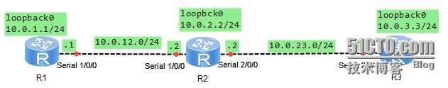
你是公司的网络管理员,公司总部有一台路由器R1、R2和R3分别是其它两个分部的路由器。现在需要将总部和分部连接到同一网络。广域网链路上尝试使用帧中继协议,在定义FR的DLCI与IP地址对应关系时采用了不同的二层和三层地址映射方式。
学习任务
步骤一.进本配置与IP编址
[Huawei]sysname R1
[R1]interface s1/0/0
[R1-Serial1/0/0]ip add 10.0.12.1 24
[R1-Serial1/0/0]desc this port connectR2-S1/0/0
[R1-Serial1/0/0]interface loopback0
[R1-LoopBack0]ip add 10.0.1.1 24
[R1-LoopBack0]q
[R1]
[Huawei]sysname R2
[R2]interface s1/0/0
[R2-Serial1/0/0]ip add 10.0.12.2 24
[R2-Serial1/0/0]desc this port connect toR1-S1/0/0
[R2-Serial1/0/0]interface s2/0/0
[R2-Serial2/0/0]ip add 10.0.23.2 24
[R2-Serial2/0/0]desc this port connect toR3-S2/0/0
[R2-Serial2/0/0]interface loopback0
[R2-LoopBack0]ip add 10.0.2.2 24
[R2-LoopBack0]q
[Huawei]sysname R3
[R3]interface s2/0/0
[R3-Serial2/0/0]ip add 10.0.23.3 24
[R3-Serial2/0/0]
Jul 3 2014 16:26:59-05:13 R3 %%01IFNET/4/LINK_STATE(l)[2]:The line protocolPPP
IPCP on the interface Serial2/0/0 hasentered the UP state.
[R3-Serial2/0/0]desc this port connect toR2-S2/0/0
[R3-Serial2/0/0]interface loopback0
[R3-LoopBack0]ip add 10.0.3.3 24
[R3-LoopBack0]q
完成后测试网络的连通性。
[R2]ping 10.0.12.1
PING 10.0.12.1: 56 data bytes,press CTRL_C to break
Reply from 10.0.12.1: bytes=56 Sequence=1 ttl=255 time=40 ms
Reply from 10.0.12.1: bytes=56 Sequence=2 ttl=255 time=10 ms
Reply from 10.0.12.1: bytes=56 Sequence=3 ttl=255 time=20 ms
Reply from 10.0.12.1: bytes=56 Sequence=4 ttl=255 time=10 ms
Reply from 10.0.12.1: bytes=56 Sequence=5 ttl=255 time=20 ms
---10.0.12.1 ping statistics ---
5packet(s) transmitted
5packet(s) received
0.00% packet loss
round-trip min/avg/max = 10/20/40 ms
[R2]ping -c 1 10.0.23.3
PING 10.0.23.3: 56 data bytes,press CTRL_C to break
Reply from 10.0.23.3: bytes=56 Sequence=1 ttl=255 time=30 ms
---10.0.23.3 ping statistics ---
1packet(s) transmitted
1packet(s) received
0.00% packet loss
round-tripmin/avg/max = 30/30/30 ms步骤二.配置R1与R2之间使用帧中继的背靠背形式,使用静态地址映射。
配置帧中继时,串口线缆的DCE端与DTE端配置不同,首先查看时R1还是R2连接到串口线缆的DCE段。
<R1>dis inter s1/0/0
Serial1/0/0 current state : UP
Line protocol current state : UP
Last line protocol up time : 2014-07-0316:22:58 UTC-05:13
Description:this port connect R2-S1/0/0
Route Port,The Maximum Transmit Unit is1500, Hold timer is 10(sec)
Internet Address is 10.0.12.1/24
Link layer protocol is PPP
LCP opened, IPCP opened
Last physical up time : 2014-07-03 16:20:52 UTC-05:13
Last physical down time : 2014-07-0316:15:31 UTC-05:13
Current system time: 2014-07-0316:30:44-05:13
Physical layer is synchronous,Virtualbaudrate is 64000 bps
Interface is DTE, Cabletype is V11, Clock mode is DCECLK
Last 300 seconds input rate 8 bytes/sec 64bits/sec 0 packets/sec
Last 300 seconds output rate 3 bytes/sec 24bits/sec 0 packets/sec
Input: 132 packets, 4614 bytes
Broadcast: 0, Multicast: 0
Errors: 0, Runts: 0
Giants: 0, CRC: 0
Alignments: 0, Overruns: 0
Dribbles: 0, Aborts: 0
NoBuffers: 0, Frame Error: 0
如以上显示R1的S1/0/0接口连接到了串行线缆的DTE端,把dte改成dce
[R1]interface s1/0/0
[R1-Serial1/0/0]link-
[R1-Serial1/0/0]link-protocol fr
Warning: The encapsulation protocol of thelink will be changed. Continue? [Y/N]:y
[R1-Serial1/0/0]fr inter
[R1-Serial1/0/0]fr interface-type dce
[R1-Serial1/0/0]undo fr inarp
[R1-Serial1/0/0]fr dlci 102
[R1-fr-dlci-Serial1/0/0-102]q
[R1-Serial1/0/0]fr map ip 10.0.12.2 102broadcast
[R1-Serial1/0/0]q
R1、R2端串行线缆的DTE端
[R1]interface s1/0/0
[R1-Serial1/0/0]link-protocol fr
Warning: The encapsulation protocol of thelink will be changed. Continue? [Y/N]:y
[R1-Serial1/0/0]fr inter
[R1-Serial1/0/0]fr interface-type dte
[R1-Serial1/0/0]undo fr inarp
[R1-Serial1/0/0]fr map ip 10.0.12.2 102 bro
[R1-Serial1/0/0]fr map ip 10.0.12.2 102broadcast
[R1-Serial1/0/0]
[R2]interface s1/0/0
[R2-Serial1/0/0]link
[R2-Serial1/0/0]link-protocol fr
Warning: The encapsulation protocol of thelink will be changed. Continue? [Y/N]:y
[R2-Serial1/0/0]fr interface-type dte
[R2-Serial1/0/0]undo fr inarp
[R2-Serial1/0/0]fr map ip 10.0.12.1 102broadcast
配置完成后,在此测试R1与R2的连通性。
[R2]ping 10.0.12.1
PING 10.0.12.1: 56 data bytes,press CTRL_C to break
Reply from 10.0.12.1: bytes=56 Sequence=1 ttl=255 time=30 ms
Reply from 10.0.12.1: bytes=56 Sequence=2 ttl=255 time=10 ms
Reply from 10.0.12.1: bytes=56 Sequence=3 ttl=255 time=10 ms
Reply from 10.0.12.1: bytes=56 Sequence=4 ttl=255 time=10 ms
Reply from 10.0.12.1: bytes=56 Sequence=5 ttl=255 time=10 ms
---10.0.12.1 ping statistics ---
5packet(s) transmitted
5packet(s) received
0.00% packet loss
round-trip min/avg/max = 10/14/30 ms
注意,如果在配置帧中继之前,在步骤一的最后。测试R1与R2通讯正常。如果不正常,则错误出现在帧中继的配置上面。可以使用如下方式进行故障排除。
以R1为例,注意以下标记的信息,并与R2对应信息对比。
<R1>dis fr ma
<R1>dis fr map-info
Map Statistics for interface Serial1/0/0(DCE)
DLCI = 102, IP10.0.12.2, Serial1/0/0
create time = 2014/07/04 04:59:39, status = ACTIVE
encapsulation =ietf, vlink = 2, broadcast<R1>dis interface s1/0/0
Serial1/0/0 current state: UP
Line protocol currentstate : UP
Last line protocol up time : 2014-07-0405:01:23 UTC-05:13
Description:this port connect to R2-S1/0/0
Route Port,The Maximum Transmit Unit is1500, Hold timer is 10(sec)
Internet Address is 10.0.12.1/24
Link layer protocol is FRIETF
LMI DLCI is 0, LMI type is Q.933a, framerelay DCE
LMIstatus enquiry received 100, LMI status sent 100
LMIstatus enquiry timeout 9, LMI message discarded 2
Last physical up time : 2014-07-04 04:58:39 UTC-05:13
Last physical down time : 2014-07-0404:58:38 UTC-05:13
Current system time: 2014-07-0405:17:54-05:13
Physical layer is synchronous,Virtualbaudrate is 64000 bps
Interface is DTE, Cable type is V11, Clockmode is TC
Last 300 seconds input rate 3 bytes/sec 24bits/sec 0 packets/sec
Last 300 seconds output rate 1 bytes/sec 8bits/sec 0 packets/sec
Input: 481 packets, 16371 bytes
Broadcast: 0, Multicast: 0
Errors: 0, Runts: 0
Giants: 0, CRC: 0
Alignments: 0, Overruns: 0
Dribbles: 0, Aborts: 0
NoBuffers: 0, Frame Error: 0
Output: 472 packets, 6642 bytes
Total Error: 0, Overruns: 0
Collisions: 0, Deferred: 0
Input bandwidth utilization : 0%
Output bandwidth utilization : 0%
<R1>dis fr lmi-info interface s1/0/0
Frame relay LMI statistics for interfaceSerial1/0/0 (DCE, Q933)
T392DCE = 15, N392DCE = 3, N393DCE = 4
instatus enquiry = 111, out status = 111
status enquiry timeout = 9, discarded messages = 2
步骤三.配置R2与R3之间使用帧中继的背靠背形式,使用动态地址映射
配置帧中继时,串口线缆的DCE端与DTE端配置不同。
查看是R2还是R3连接到串口线缆的dce段。
<R3>dis interface s2/0/0
Serial2/0/0 current state : UP
Line protocol current state : UP
Last line protocol up time : 2014-07-0404:34:05 UTC-05:13
Description:this port connect to R2-S2/0/0
Route Port,The Maximum Transmit Unit is1500, Hold timer is 10(sec)
Internet Address is 10.0.23.3/24
Link layer protocol is PPP
LCP opened, IPCP opened
Last physical up time : 2014-07-04 04:33:28 UTC-05:13
Last physical down time : 2014-07-0404:33:25 UTC-05:13
Current system time: 2014-07-0405:22:38-05:13
Physical layer is synchronous,Virtualbaudrate is 64000 bps
Interface is DTE, Cabletype is V11, Clock mode is TC
Last 300 seconds input rate 6 bytes/sec 48bits/sec 0 packets/sec
Last 300 seconds output rate 2 bytes/sec 16bits/sec 0 packets/sec
Input: 599 packets, 19568 bytes
Broadcast: 0, Multicast: 0
Errors: 0, Runts: 0
Giants: 0, CRC: 0
Alignments: 0, Overruns: 0
Dribbles: 0, Aborts: 0
NoBuffers: 0, Frame Error: 0
经过查看两端都为DTE端。先配置R2S2/0/0。
[R2]interface s2/0/0
[R2-Serial2/0/0]link-
[R2-Serial2/0/0]link-protocol fr
Warning: The encapsulation protocol of thelink will be changed. Continue? [Y/N]:y
[R2-Serial2/0/0]fr interface-type dte
[R2-Serial2/0/0]fr inarp
R3端为DCE。
[R3]interface s2/0/0
[R3-Serial2/0/0]lin
[R3-Serial2/0/0]link-protocol fr
Warning: The encapsulation protocol of thelink will be changed. Continue? [Y/N]:y
[R3-Serial2/0/0]fr interface-type dce
[R3-Serial2/0/0]fr dlci 203
[R3-fr-dlci-Serial2/0/0-203]q
[R3-Serial2/0/0]fr inarp
[R3-Serial2/0/0]q
配置完成后,测试R2与R3之间的连通性
[R3]ping -c 1 10.0.23.2
PING 10.0.23.2: 56 data bytes,press CTRL_C to break
Reply from 10.0.23.2: bytes=56 Sequence=1 ttl=255 time=10 ms
---10.0.23.2 ping statistics ---
1packet(s) transmitted
1packet(s) received
0.00% packet loss
round-tripmin/avg/max = 10/10/10 ms步骤四.配置R1与R2之间运行RIPv2,手动定义邻居关系
[R1]rip
[R1-rip-1]version 2
[R1-rip-1]network 10.0.0.0
[R1-rip-1]undo summary
[R2]rip
[R2-rip-1]version 2
[R2-rip-1]network 10.0.0.0
[R2-rip-1]undo summary
在R1上查看路由信息
[R1]dis ip routing-table
Route Flags: R - relay, D - download to fib
------------------------------------------------------------------------------
Routing Tables: Public
Destinations : 13 Routes :13
Destination/Mask Proto Pre Cost Flags NextHop Interface
10.0.1.0/24 Direct 0 0 D 10.0.1.1 LoopBack0
10.0.1.1/32 Direct 0 0 D 127.0.0.1 LoopBack0
10.0.1.255/32 Direct 0 0 D 127.0.0.1 LoopBack0
10.0.2.0/24 RIP 100 1 D 10.0.12.2 Serial1/0/0
10.0.12.0/24 Direct 0 0 D 10.0.12.1 Serial1/0/0
10.0.12.1/32 Direct 0 0 D 127.0.0.1 Serial1/0/0
10.0.12.2/32 Direct 0 0 D 10.0.12.2 Serial1/0/0
10.0.12.255/32 Direct 0 0 D 127.0.0.1 Serial1/0/0
10.0.23.0/24 RIP 100 1 D 10.0.12.2 Serial1/0/0
127.0.0.0/8 Direct 0 0 D 127.0.0.1 InLoopBack0
127.0.0.1/32 Direct 0 0 D 127.0.0.1 InLoopBack0
127.255.255.255/32 Direct 0 0 D 127.0.0.1 InLoopBack0
255.255.255.255/32 Direct 0 0 D 127.0.0.1 InLoopBack0
如上所示R1已经学习到了路由信息。在R1上测试网络的联通情况。
[R1]ping -c 1 10.0.23.2
PING 10.0.23.2: 56 data bytes,press CTRL_C to break
Reply from 10.0.23.2: bytes=56 Sequence=1 ttl=255 time=20 ms
---10.0.23.2 ping statistics ---
1packet(s) transmitted
1packet(s) received
0.00% packet loss
round-tripmin/avg/max = 20/20/20 ms显示通讯正常。注意此时R3未运行任何协议,R1将无法与R3通讯。此时R1与R2运行RIPv2协议,但是由于网络支持广播,所以可以自动相互发送路由信息。网络对广播支持的查看,一R2为例。<R2>dis frmap-info interface s1/0/0Map Statisticsfor interface Serial1/0/0 (DTE) DLCI = 102, IP 10.0.12.1, Serial1/0/0 create time = 2014/07/04 05:02:02, status =ACTIVE encapsulation = ietf, vlink = 3, broadcast修改R1与R2配置,关闭对广播的支持。
[R1]interface s1/0/0
[R1-Serial1/0/0]undo fr map ip 10.0.12.2102
[R1-Serial1/0/0]fr map ip 10.0.12.2 102
[R2]interface s1/0/0
[R2-Serial1/0/0]undo fr map ip 10.0.12.1102
[R2-Serial1/0/0]fr map ip 10.0.12.1 102
为使R1与R2刷新路由学习情况,需要将其中一个设备的接口关闭然后在打开。这里以R2为例。
[R2-Serial1/0/0]shutdown
[R2-Serial1/0/0]undo shutdown
完成后。在查看路由信息,以R2为例。
[R2]dis ip routing-table
Route Flags: R - relay, D - download to fib
------------------------------------------------------------------------------
Routing Tables: Public
Destinations : 15 Routes :15
Destination/Mask Proto Pre Cost Flags NextHop Interface
10.0.2.0/24 Direct 0 0 D 10.0.2.2 LoopBack0
10.0.2.2/32 Direct 0 0 D 127.0.0.1 LoopBack0
10.0.2.255/32 Direct 0 0 D 127.0.0.1 LoopBack0
10.0.12.0/24 Direct 0 0 D 10.0.12.2 Serial1/0/0
10.0.12.1/32 Direct 0 0 D 10.0.12.1 Serial1/0/0
10.0.12.2/32 Direct 0 0 D 127.0.0.1 Serial1/0/0
10.0.12.255/32 Direct 0 0 D 127.0.0.1 Serial1/0/0
10.0.23.0/24 Direct 0 0 D 10.0.23.2 Serial2/0/0
10.0.23.2/32 Direct 0 0 D 127.0.0.1 Serial2/0/0
10.0.23.3/32 Direct 0 0 D 10.0.23.3 Serial2/0/0
10.0.23.255/32 Direct 0 0 D 127.0.0.1 Serial2/0/0
127.0.0.0/8 Direct 0 0 D 127.0.0.1 InLoopBack0
127.0.0.1/32 Direct 0 0 D 127.0.0.1 InLoopBack0
127.255.255.255/32 Direct 0 0 D 127.0.0.1 InLoopBack0
255.255.255.255/32 Direct 0 0 D 127.0.0.1 InLoopBack0
注意,此时,由于网络不支持广播。R1与R2无法相互交流路由信息。使用ping测试。
[R2]ping 10.0.1.1
PING 10.0.1.1: 56 data bytes,press CTRL_C to break
Request time out
Request time out
Request time out
Request time out
Request time out
---10.0.1.1 ping statistics ---
5packet(s) transmitted
0packet(s) received
100.00% packetloss此时网络不支持广播,以R2为例。[R2]dis frmap-info interface s1/0/0Map Statisticsfor interface Serial1/0/0 (DTE) DLCI = 102, IP 10.0.12.1, Serial1/0/0 create time = 2014/07/04 05:44:28, status =ACTIVE encapsulation = ietf, vlink = 6注意这里无broadcast字段手动定义R1与R2相互为RIP邻居,使用单播交换路由信息。[R1]rip[R1-rip-1]peer10.0.12.2[R1-rip-1]q [R2]rip[R2-rip-1]peer10.0.12.1[R2-rip-1]q配置完成后,在R2上查看路由信息。[R2]dis iprouting-tableRoute Flags: R -relay, D - download to fib------------------------------------------------------------------------------Routing Tables:Public Destinations : 16 Routes : 16 Destination/Mask Proto Pre Cost Flags NextHop Interface 10.0.1.0/24 RIP 100 1 D 10.0.12.1 Serial1/0/0 10.0.2.0/24 Direct 0 0 D 10.0.2.2 LoopBack0 10.0.2.2/32 Direct 0 0 D 127.0.0.1 LoopBack0 10.0.2.255/32 Direct 0 0 D 127.0.0.1 LoopBack0 10.0.12.0/24 Direct 0 0 D 10.0.12.2 Serial1/0/0 10.0.12.1/32 Direct 0 0 D 10.0.12.1 Serial1/0/0 10.0.12.2/32 Direct 0 0 D 127.0.0.1 Serial1/0/0 10.0.12.255/32 Direct 0 0 D 127.0.0.1 Serial1/0/0 10.0.23.0/24 Direct 0 0 D 10.0.23.2 Serial2/0/0 10.0.23.2/32 Direct 0 0 D 127.0.0.1 Serial2/0/0 10.0.23.3/32 Direct 0 0 D 10.0.23.3 Serial2/0/0 10.0.23.255/32 Direct 0 0 D 127.0.0.1 Serial2/0/0 127.0.0.0/8 Direct 0 0 D 127.0.0.1 InLoopBack0 127.0.0.1/32 Direct 0 0 D 127.0.0.1 InLoopBack0127.255.255.255/32 Direct 0 0 D 127.0.0.1 InLoopBack0255.255.255.255/32 Direct 0 0 D 127.0.0.1 InLoopBack0使用ping命令进行连通性测试。[R2]ping -c 110.0.1.1 PING 10.0.1.1: 56 data bytes, press CTRL_C to break Reply from 10.0.1.1: bytes=56 Sequence=1ttl=255 time=10 ms --- 10.0.1.1 ping statistics --- 1 packet(s) transmitted 1 packet(s) received 0.00% packet loss round-trip min/avg/max = 10/10/10 ms注意:有RIPv2协议默认进行网络汇总,所以在R1设备上看路由信息时,只有一条RIP路由。步骤五.配置R2与R3之间运行ospf,手动定义邻居关系。[R2]router id10.0.2.2Info: Router IDhas been modified, please reset the relative protocols manually to update theRouter ID.[R2]ospf 1[R2-ospf-1]area0[R2-ospf-1-area-0.0.0.0]network10.0.0.0 0.255.255.255 [R3]router id10.0.3.3Info: Router IDhas been modified, please reset the relative protocols manually to update theRouter ID.[R3]ospf 1[R3-ospf-1]area0[R3-ospf-1-area-0.0.0.0]network10.0.0.0 0.255.255.255[R3-ospf-1-area-0.0.0.0]q配置完成后,以R3为例查看路由信息。[R3]dis iprouting-tableRoute Flags: R -relay, D - download to fib------------------------------------------------------------------------------Routing Tables:Public Destinations : 11 Routes : 11 Destination/Mask Proto Pre Cost Flags NextHop Interface 10.0.3.0/24 Direct 0 0 D 10.0.3.3 LoopBack0 10.0.3.3/32 Direct 0 0 D 127.0.0.1 LoopBack0 10.0.3.255/32 Direct 0 0 D 127.0.0.1 LoopBack0 10.0.23.0/24 Direct 0 0 D 10.0.23.3 Serial2/0/0 10.0.23.2/32 Direct 0 0 D 10.0.23.2 Serial2/0/0 10.0.23.3/32 Direct 0 0 D 127.0.0.1 Serial2/0/0 10.0.23.255/32 Direct 0 0 D 127.0.0.1 Serial2/0/0 127.0.0.0/8 Direct 0 0 D 127.0.0.1 InLoopBack0 127.0.0.1/32 Direct 0 0 D 127.0.0.1 InLoopBack0127.255.255.255/32 Direct 0 0 D 127.0.0.1 InLoopBack0255.255.255.255/32 Direct 0 0 D 127.0.0.1 InLoopBack0注意这里没有学习到R2发送过来的路由信息。默认情况下,ospf认为的封装为帧中继的接口网络模式为“NBMA”,默认不主动发现邻居。[R3]dis ospfinterface s2/0/0 OSPF Process 1 with Router ID 10.0.3.3 Interfaces Interface: 10.0.23.3 (Serial2/0/0) Cost: 48 State: DR Type: NBMA MTU: 1500 Priority: 1 Designated Router: 10.0.23.3 Backup Designated Router: 0.0.0.0 Timers: Hello 30 , Dead 120 , Poll 120 , Retransmit 5 , Transmit Delay 1以R3为例,查看OSPF尽力的邻居关系[R3]dis ospfpeer OSPF Process 1 with Router ID 10.0.3.3在这种情况下,为能自动发现邻居关系,必须手动定义邻居关系。[R2]ospf 1[R2-ospf-1]peer10.0.23.3 [R3]ospf 1[R3-ospf-1]peer10.0.23.2配置完成后查看R3的OSPF邻居关系[R3]dis ospfpeer OSPF Process 1 with Router ID 10.0.3.3 Neighbors Area 0.0.0.0 interface10.0.23.3(Serial2/0/0)'s neighbors Router ID: 10.0.2.2 Address: 10.0.23.2 State: Full Mode:Nbr is Slave Priority: 1 DR: 10.0.23.3 BDR: 10.0.23.2 MTU: 0 Dead timer due in 93 sec Retrans timer interval: 5 Neighbor is up for 00:01:55 Authentication Sequence: [ 0 ]此时邻居关系已经建立。以R3为例,查看路由表信息。[R3]dis iprouting-tableRoute Flags: R -relay, D - download to fib------------------------------------------------------------------------------Routing Tables:Public Destinations : 13 Routes : 13 Destination/Mask Proto Pre Cost Flags NextHop Interface 10.0.2.2/32 OSPF 10 48 D 10.0.23.2 Serial2/0/0 10.0.3.0/24 Direct 0 0 D 10.0.3.3 LoopBack0 10.0.3.3/32 Direct 0 0 D 127.0.0.1 LoopBack0 10.0.3.255/32 Direct 0 0 D 127.0.0.1 LoopBack0 10.0.12.0/24 OSPF 10 96 D 10.0.23.2 Serial2/0/0 10.0.23.0/24 Direct 0 0 D 10.0.23.3 Serial2/0/0 10.0.23.2/32 Direct 0 0 D 10.0.23.2 Serial2/0/0 10.0.23.3/32 Direct 0 0 D 127.0.0.1 Serial2/0/0 10.0.23.255/32 Direct 0 0 D 127.0.0.1 Serial2/0/0 127.0.0.0/8 Direct 0 0 D 127.0.0.1 InLoopBack0 127.0.0.1/32 Direct 0 0 D 127.0.0.1 InLoopBack0127.255.255.255/32 Direct 0 0 D 127.0.0.1 InLoopBack0255.255.255.255/32 Direct 0 0 D 127.0.0.1 InLoopBack0测试R3与R2的连通性[R3]ping -c 110.0.2.2 PING 10.0.2.2: 56 data bytes, press CTRL_C to break Reply from 10.0.2.2: bytes=56 Sequence=1ttl=255 time=10 ms --- 10.0.2.2 ping statistics --- 1 packet(s) transmitted 1 packet(s) received 0.00% packet loss round-trip min/avg/max = 10/10/10 ms步骤六.配置R2与R3之间运行OSPF,不定义邻居关系,修改网络类型为广播。 在帧中继网络上运行OSPF。可以手动定义邻居,也可以在支持广播的网络上定义OSPF自动发现邻居的功能。删除任务5中R2与R3关于手动邻居关系的定义。[R2]ospf 1[R2-ospf-1]undopeer 10.0.23.3 [R3]ospf 1[R3-ospf-1]undopeer 10.0.23.2确认帧中继接口支持广播功能。[R3]dis frmap-info interface s2/0/0Map Statisticsfor interface Serial2/0/0 (DCE) DLCI = 203, IP INARP 10.0.23.2, Serial2/0/0 create time = 2014/07/04 05:29:24, status =ACTIVE encapsulation = ietf, vlink = 2, broadcast确认广播功能后,确认接口的OSPF网络类型[R3]dis fr map-info interface s2/0/0Map Statistics for interfaceSerial2/0/0 (DCE) DLCI = 203, IP INARP 10.0.23.2, Serial2/0/0 create time = 2014/07/04 05:29:24, status = ACTIVE encapsulation = ietf, vlink = 2, broadcast[R3]dis ospf interfa [R3]dis ospf interface s2/0/0 OSPF Process 1 with Router ID 10.0.3.3 Interfaces Interface: 10.0.23.3 (Serial2/0/0) Cost: 48 State: DR Type: NBMA MTU: 1500 Priority: 1 Designated Router: 10.0.23.3 Backup Designated Router: 0.0.0.0 Timers: Hello 30 , Dead 120 , Poll 120 , Retransmit 5 , Transmit Delay 1修改该网络类型为广播[R2]interface s2/0/0[R2-Serial2/0/0]ospf network-typebroadcast [R3]interface s2/0/0[R3-Serial2/0/0]ospf network-typebroadcast完成后关闭R3的S2/0/0接口,人后在打开,以便刷新邻居关系。[R3-Serial2/0/0]shutdown[R3-Serial2/0/0]undo shutdown配置完成后,稍等片刻,待OSPF邻居关系建立后,查看OSPF邻居关系。[R3]dis ospf peer OSPF Process 1 with Router ID 10.0.3.3 Neighbors Area 0.0.0.0 interface10.0.23.3(Serial2/0/0)'s neighbors Router ID: 10.0.2.2 Address: 10.0.23.2 State: Full Mode:Nbr is Slave Priority: 1 DR: 10.0.23.3 BDR: 10.0.23.2 MTU: 0 Dead timer due in 35 sec Retrans timer interval: 5 Neighbor is up for 00:00:20 Authentication Sequence: [ 0 ]以R3为例,参看路由信息,并测试R3与R2的连通性。[R3]disp ip routing-tableRoute Flags: R - relay, D - downloadto fib------------------------------------------------------------------------------Routing Tables: Public Destinations : 13 Routes : 13 Destination/Mask Proto Pre Cost Flags NextHop Interface 10.0.2.2/32 OSPF 10 48 D 10.0.23.2 Serial2/0/0 10.0.3.0/24 Direct 0 0 D 10.0.3.3 LoopBack0 10.0.3.3/32 Direct 0 0 D 127.0.0.1 LoopBack0 10.0.3.255/32 Direct 0 0 D 127.0.0.1 LoopBack0 10.0.12.0/24 OSPF 10 96 D 10.0.23.2 Serial2/0/0 10.0.23.0/24 Direct 0 0 D 10.0.23.3 Serial2/0/0 10.0.23.2/32 Direct 0 0 D 10.0.23.2 Serial2/0/0 10.0.23.3/32 Direct 0 0 D 127.0.0.1 Serial2/0/0 10.0.23.255/32 Direct 0 0 D 127.0.0.1 Serial2/0/0 127.0.0.0/8 Direct 0 0 D 127.0.0.1 InLoopBack0 127.0.0.1/32 Direct 0 0 D 127.0.0.1 InLoopBack0127.255.255.255/32 Direct 0 0 D 127.0.0.1 InLoopBack0255.255.255.255/32 Direct 0 0 D 127.0.0.1 InLoopBack0 [R3]disp ospf interface s2/0/0 OSPF Process 1 with Router ID 10.0.3.3 Interfaces Interface: 10.0.23.3 (Serial2/0/0) Cost: 48 State: DR Type: Broadcast MTU: 1500 Priority: 1 Designated Router: 10.0.23.3 Backup Designated Router: 10.0.23.2 Timers: Hello 10 , Dead 40 , Poll 120 , Retransmit 5 , Transmit Delay 1 [R3]ping -c 1 10.0.2.2 PING 10.0.2.2: 56 data bytes,press CTRL_C to break Reply from 10.0.2.2: bytes=56 Sequence=1 ttl=255 time=10 ms --- 10.0.2.2 ping statistics --- 1 packet(s) transmitted 1 packet(s) received 0.00% packet loss round-trip min/avg/max = 10/10/10 ms
附件:http://down.51cto.com/data/2364615
了解帧中继中PVC的功能
理解帧中继协议的工作原理
掌握在串行链路上配置FrameRelay的方法
掌握在帧中继网络上手动定义IP与DLCI号码映射的方法
掌握在帧中继网络上运行RIP的配置方法
掌握在帧中继网络上运行OSPF的配置方法
拓扑图
场景
你是公司的网络管理员,公司总部有一台路由器R1、R2和R3分别是其它两个分部的路由器。现在需要将总部和分部连接到同一网络。广域网链路上尝试使用帧中继协议,在定义FR的DLCI与IP地址对应关系时采用了不同的二层和三层地址映射方式。
学习任务
步骤一.进本配置与IP编址
[Huawei]sysname R1
[R1]interface s1/0/0
[R1-Serial1/0/0]ip add 10.0.12.1 24
[R1-Serial1/0/0]desc this port connectR2-S1/0/0
[R1-Serial1/0/0]interface loopback0
[R1-LoopBack0]ip add 10.0.1.1 24
[R1-LoopBack0]q
[R1]
[Huawei]sysname R2
[R2]interface s1/0/0
[R2-Serial1/0/0]ip add 10.0.12.2 24
[R2-Serial1/0/0]desc this port connect toR1-S1/0/0
[R2-Serial1/0/0]interface s2/0/0
[R2-Serial2/0/0]ip add 10.0.23.2 24
[R2-Serial2/0/0]desc this port connect toR3-S2/0/0
[R2-Serial2/0/0]interface loopback0
[R2-LoopBack0]ip add 10.0.2.2 24
[R2-LoopBack0]q
[Huawei]sysname R3
[R3]interface s2/0/0
[R3-Serial2/0/0]ip add 10.0.23.3 24
[R3-Serial2/0/0]
Jul 3 2014 16:26:59-05:13 R3 %%01IFNET/4/LINK_STATE(l)[2]:The line protocolPPP
IPCP on the interface Serial2/0/0 hasentered the UP state.
[R3-Serial2/0/0]desc this port connect toR2-S2/0/0
[R3-Serial2/0/0]interface loopback0
[R3-LoopBack0]ip add 10.0.3.3 24
[R3-LoopBack0]q
完成后测试网络的连通性。
[R2]ping 10.0.12.1
PING 10.0.12.1: 56 data bytes,press CTRL_C to break
Reply from 10.0.12.1: bytes=56 Sequence=1 ttl=255 time=40 ms
Reply from 10.0.12.1: bytes=56 Sequence=2 ttl=255 time=10 ms
Reply from 10.0.12.1: bytes=56 Sequence=3 ttl=255 time=20 ms
Reply from 10.0.12.1: bytes=56 Sequence=4 ttl=255 time=10 ms
Reply from 10.0.12.1: bytes=56 Sequence=5 ttl=255 time=20 ms
---10.0.12.1 ping statistics ---
5packet(s) transmitted
5packet(s) received
0.00% packet loss
round-trip min/avg/max = 10/20/40 ms
[R2]ping -c 1 10.0.23.3
PING 10.0.23.3: 56 data bytes,press CTRL_C to break
Reply from 10.0.23.3: bytes=56 Sequence=1 ttl=255 time=30 ms
---10.0.23.3 ping statistics ---
1packet(s) transmitted
1packet(s) received
0.00% packet loss
round-tripmin/avg/max = 30/30/30 ms步骤二.配置R1与R2之间使用帧中继的背靠背形式,使用静态地址映射。
配置帧中继时,串口线缆的DCE端与DTE端配置不同,首先查看时R1还是R2连接到串口线缆的DCE段。
<R1>dis inter s1/0/0
Serial1/0/0 current state : UP
Line protocol current state : UP
Last line protocol up time : 2014-07-0316:22:58 UTC-05:13
Description:this port connect R2-S1/0/0
Route Port,The Maximum Transmit Unit is1500, Hold timer is 10(sec)
Internet Address is 10.0.12.1/24
Link layer protocol is PPP
LCP opened, IPCP opened
Last physical up time : 2014-07-03 16:20:52 UTC-05:13
Last physical down time : 2014-07-0316:15:31 UTC-05:13
Current system time: 2014-07-0316:30:44-05:13
Physical layer is synchronous,Virtualbaudrate is 64000 bps
Interface is DTE, Cabletype is V11, Clock mode is DCECLK
Last 300 seconds input rate 8 bytes/sec 64bits/sec 0 packets/sec
Last 300 seconds output rate 3 bytes/sec 24bits/sec 0 packets/sec
Input: 132 packets, 4614 bytes
Broadcast: 0, Multicast: 0
Errors: 0, Runts: 0
Giants: 0, CRC: 0
Alignments: 0, Overruns: 0
Dribbles: 0, Aborts: 0
NoBuffers: 0, Frame Error: 0
如以上显示R1的S1/0/0接口连接到了串行线缆的DTE端,把dte改成dce
[R1]interface s1/0/0
[R1-Serial1/0/0]link-
[R1-Serial1/0/0]link-protocol fr
Warning: The encapsulation protocol of thelink will be changed. Continue? [Y/N]:y
[R1-Serial1/0/0]fr inter
[R1-Serial1/0/0]fr interface-type dce
[R1-Serial1/0/0]undo fr inarp
[R1-Serial1/0/0]fr dlci 102
[R1-fr-dlci-Serial1/0/0-102]q
[R1-Serial1/0/0]fr map ip 10.0.12.2 102broadcast
[R1-Serial1/0/0]q
R1、R2端串行线缆的DTE端
[R1]interface s1/0/0
[R1-Serial1/0/0]link-protocol fr
Warning: The encapsulation protocol of thelink will be changed. Continue? [Y/N]:y
[R1-Serial1/0/0]fr inter
[R1-Serial1/0/0]fr interface-type dte
[R1-Serial1/0/0]undo fr inarp
[R1-Serial1/0/0]fr map ip 10.0.12.2 102 bro
[R1-Serial1/0/0]fr map ip 10.0.12.2 102broadcast
[R1-Serial1/0/0]
[R2]interface s1/0/0
[R2-Serial1/0/0]link
[R2-Serial1/0/0]link-protocol fr
Warning: The encapsulation protocol of thelink will be changed. Continue? [Y/N]:y
[R2-Serial1/0/0]fr interface-type dte
[R2-Serial1/0/0]undo fr inarp
[R2-Serial1/0/0]fr map ip 10.0.12.1 102broadcast
配置完成后,在此测试R1与R2的连通性。
[R2]ping 10.0.12.1
PING 10.0.12.1: 56 data bytes,press CTRL_C to break
Reply from 10.0.12.1: bytes=56 Sequence=1 ttl=255 time=30 ms
Reply from 10.0.12.1: bytes=56 Sequence=2 ttl=255 time=10 ms
Reply from 10.0.12.1: bytes=56 Sequence=3 ttl=255 time=10 ms
Reply from 10.0.12.1: bytes=56 Sequence=4 ttl=255 time=10 ms
Reply from 10.0.12.1: bytes=56 Sequence=5 ttl=255 time=10 ms
---10.0.12.1 ping statistics ---
5packet(s) transmitted
5packet(s) received
0.00% packet loss
round-trip min/avg/max = 10/14/30 ms
注意,如果在配置帧中继之前,在步骤一的最后。测试R1与R2通讯正常。如果不正常,则错误出现在帧中继的配置上面。可以使用如下方式进行故障排除。
以R1为例,注意以下标记的信息,并与R2对应信息对比。
<R1>dis fr ma
<R1>dis fr map-info
Map Statistics for interface Serial1/0/0(DCE)
DLCI = 102, IP10.0.12.2, Serial1/0/0
create time = 2014/07/04 04:59:39, status = ACTIVE
encapsulation =ietf, vlink = 2, broadcast<R1>dis interface s1/0/0
Serial1/0/0 current state: UP
Line protocol currentstate : UP
Last line protocol up time : 2014-07-0405:01:23 UTC-05:13
Description:this port connect to R2-S1/0/0
Route Port,The Maximum Transmit Unit is1500, Hold timer is 10(sec)
Internet Address is 10.0.12.1/24
Link layer protocol is FRIETF
LMI DLCI is 0, LMI type is Q.933a, framerelay DCE
LMIstatus enquiry received 100, LMI status sent 100
LMIstatus enquiry timeout 9, LMI message discarded 2
Last physical up time : 2014-07-04 04:58:39 UTC-05:13
Last physical down time : 2014-07-0404:58:38 UTC-05:13
Current system time: 2014-07-0405:17:54-05:13
Physical layer is synchronous,Virtualbaudrate is 64000 bps
Interface is DTE, Cable type is V11, Clockmode is TC
Last 300 seconds input rate 3 bytes/sec 24bits/sec 0 packets/sec
Last 300 seconds output rate 1 bytes/sec 8bits/sec 0 packets/sec
Input: 481 packets, 16371 bytes
Broadcast: 0, Multicast: 0
Errors: 0, Runts: 0
Giants: 0, CRC: 0
Alignments: 0, Overruns: 0
Dribbles: 0, Aborts: 0
NoBuffers: 0, Frame Error: 0
Output: 472 packets, 6642 bytes
Total Error: 0, Overruns: 0
Collisions: 0, Deferred: 0
Input bandwidth utilization : 0%
Output bandwidth utilization : 0%
<R1>dis fr lmi-info interface s1/0/0
Frame relay LMI statistics for interfaceSerial1/0/0 (DCE, Q933)
T392DCE = 15, N392DCE = 3, N393DCE = 4
instatus enquiry = 111, out status = 111
status enquiry timeout = 9, discarded messages = 2
步骤三.配置R2与R3之间使用帧中继的背靠背形式,使用动态地址映射
配置帧中继时,串口线缆的DCE端与DTE端配置不同。
查看是R2还是R3连接到串口线缆的dce段。
<R3>dis interface s2/0/0
Serial2/0/0 current state : UP
Line protocol current state : UP
Last line protocol up time : 2014-07-0404:34:05 UTC-05:13
Description:this port connect to R2-S2/0/0
Route Port,The Maximum Transmit Unit is1500, Hold timer is 10(sec)
Internet Address is 10.0.23.3/24
Link layer protocol is PPP
LCP opened, IPCP opened
Last physical up time : 2014-07-04 04:33:28 UTC-05:13
Last physical down time : 2014-07-0404:33:25 UTC-05:13
Current system time: 2014-07-0405:22:38-05:13
Physical layer is synchronous,Virtualbaudrate is 64000 bps
Interface is DTE, Cabletype is V11, Clock mode is TC
Last 300 seconds input rate 6 bytes/sec 48bits/sec 0 packets/sec
Last 300 seconds output rate 2 bytes/sec 16bits/sec 0 packets/sec
Input: 599 packets, 19568 bytes
Broadcast: 0, Multicast: 0
Errors: 0, Runts: 0
Giants: 0, CRC: 0
Alignments: 0, Overruns: 0
Dribbles: 0, Aborts: 0
NoBuffers: 0, Frame Error: 0
经过查看两端都为DTE端。先配置R2S2/0/0。
[R2]interface s2/0/0
[R2-Serial2/0/0]link-
[R2-Serial2/0/0]link-protocol fr
Warning: The encapsulation protocol of thelink will be changed. Continue? [Y/N]:y
[R2-Serial2/0/0]fr interface-type dte
[R2-Serial2/0/0]fr inarp
R3端为DCE。
[R3]interface s2/0/0
[R3-Serial2/0/0]lin
[R3-Serial2/0/0]link-protocol fr
Warning: The encapsulation protocol of thelink will be changed. Continue? [Y/N]:y
[R3-Serial2/0/0]fr interface-type dce
[R3-Serial2/0/0]fr dlci 203
[R3-fr-dlci-Serial2/0/0-203]q
[R3-Serial2/0/0]fr inarp
[R3-Serial2/0/0]q
配置完成后,测试R2与R3之间的连通性
[R3]ping -c 1 10.0.23.2
PING 10.0.23.2: 56 data bytes,press CTRL_C to break
Reply from 10.0.23.2: bytes=56 Sequence=1 ttl=255 time=10 ms
---10.0.23.2 ping statistics ---
1packet(s) transmitted
1packet(s) received
0.00% packet loss
round-tripmin/avg/max = 10/10/10 ms步骤四.配置R1与R2之间运行RIPv2,手动定义邻居关系
[R1]rip
[R1-rip-1]version 2
[R1-rip-1]network 10.0.0.0
[R1-rip-1]undo summary
[R2]rip
[R2-rip-1]version 2
[R2-rip-1]network 10.0.0.0
[R2-rip-1]undo summary
在R1上查看路由信息
[R1]dis ip routing-table
Route Flags: R - relay, D - download to fib
------------------------------------------------------------------------------
Routing Tables: Public
Destinations : 13 Routes :13
Destination/Mask Proto Pre Cost Flags NextHop Interface
10.0.1.0/24 Direct 0 0 D 10.0.1.1 LoopBack0
10.0.1.1/32 Direct 0 0 D 127.0.0.1 LoopBack0
10.0.1.255/32 Direct 0 0 D 127.0.0.1 LoopBack0
10.0.2.0/24 RIP 100 1 D 10.0.12.2 Serial1/0/0
10.0.12.0/24 Direct 0 0 D 10.0.12.1 Serial1/0/0
10.0.12.1/32 Direct 0 0 D 127.0.0.1 Serial1/0/0
10.0.12.2/32 Direct 0 0 D 10.0.12.2 Serial1/0/0
10.0.12.255/32 Direct 0 0 D 127.0.0.1 Serial1/0/0
10.0.23.0/24 RIP 100 1 D 10.0.12.2 Serial1/0/0
127.0.0.0/8 Direct 0 0 D 127.0.0.1 InLoopBack0
127.0.0.1/32 Direct 0 0 D 127.0.0.1 InLoopBack0
127.255.255.255/32 Direct 0 0 D 127.0.0.1 InLoopBack0
255.255.255.255/32 Direct 0 0 D 127.0.0.1 InLoopBack0
如上所示R1已经学习到了路由信息。在R1上测试网络的联通情况。
[R1]ping -c 1 10.0.23.2
PING 10.0.23.2: 56 data bytes,press CTRL_C to break
Reply from 10.0.23.2: bytes=56 Sequence=1 ttl=255 time=20 ms
---10.0.23.2 ping statistics ---
1packet(s) transmitted
1packet(s) received
0.00% packet loss
round-tripmin/avg/max = 20/20/20 ms显示通讯正常。注意此时R3未运行任何协议,R1将无法与R3通讯。此时R1与R2运行RIPv2协议,但是由于网络支持广播,所以可以自动相互发送路由信息。网络对广播支持的查看,一R2为例。<R2>dis frmap-info interface s1/0/0Map Statisticsfor interface Serial1/0/0 (DTE) DLCI = 102, IP 10.0.12.1, Serial1/0/0 create time = 2014/07/04 05:02:02, status =ACTIVE encapsulation = ietf, vlink = 3, broadcast修改R1与R2配置,关闭对广播的支持。
[R1]interface s1/0/0
[R1-Serial1/0/0]undo fr map ip 10.0.12.2102
[R1-Serial1/0/0]fr map ip 10.0.12.2 102
[R2]interface s1/0/0
[R2-Serial1/0/0]undo fr map ip 10.0.12.1102
[R2-Serial1/0/0]fr map ip 10.0.12.1 102
为使R1与R2刷新路由学习情况,需要将其中一个设备的接口关闭然后在打开。这里以R2为例。
[R2-Serial1/0/0]shutdown
[R2-Serial1/0/0]undo shutdown
完成后。在查看路由信息,以R2为例。
[R2]dis ip routing-table
Route Flags: R - relay, D - download to fib
------------------------------------------------------------------------------
Routing Tables: Public
Destinations : 15 Routes :15
Destination/Mask Proto Pre Cost Flags NextHop Interface
10.0.2.0/24 Direct 0 0 D 10.0.2.2 LoopBack0
10.0.2.2/32 Direct 0 0 D 127.0.0.1 LoopBack0
10.0.2.255/32 Direct 0 0 D 127.0.0.1 LoopBack0
10.0.12.0/24 Direct 0 0 D 10.0.12.2 Serial1/0/0
10.0.12.1/32 Direct 0 0 D 10.0.12.1 Serial1/0/0
10.0.12.2/32 Direct 0 0 D 127.0.0.1 Serial1/0/0
10.0.12.255/32 Direct 0 0 D 127.0.0.1 Serial1/0/0
10.0.23.0/24 Direct 0 0 D 10.0.23.2 Serial2/0/0
10.0.23.2/32 Direct 0 0 D 127.0.0.1 Serial2/0/0
10.0.23.3/32 Direct 0 0 D 10.0.23.3 Serial2/0/0
10.0.23.255/32 Direct 0 0 D 127.0.0.1 Serial2/0/0
127.0.0.0/8 Direct 0 0 D 127.0.0.1 InLoopBack0
127.0.0.1/32 Direct 0 0 D 127.0.0.1 InLoopBack0
127.255.255.255/32 Direct 0 0 D 127.0.0.1 InLoopBack0
255.255.255.255/32 Direct 0 0 D 127.0.0.1 InLoopBack0
注意,此时,由于网络不支持广播。R1与R2无法相互交流路由信息。使用ping测试。
[R2]ping 10.0.1.1
PING 10.0.1.1: 56 data bytes,press CTRL_C to break
Request time out
Request time out
Request time out
Request time out
Request time out
---10.0.1.1 ping statistics ---
5packet(s) transmitted
0packet(s) received
100.00% packetloss此时网络不支持广播,以R2为例。[R2]dis frmap-info interface s1/0/0Map Statisticsfor interface Serial1/0/0 (DTE) DLCI = 102, IP 10.0.12.1, Serial1/0/0 create time = 2014/07/04 05:44:28, status =ACTIVE encapsulation = ietf, vlink = 6注意这里无broadcast字段手动定义R1与R2相互为RIP邻居,使用单播交换路由信息。[R1]rip[R1-rip-1]peer10.0.12.2[R1-rip-1]q [R2]rip[R2-rip-1]peer10.0.12.1[R2-rip-1]q配置完成后,在R2上查看路由信息。[R2]dis iprouting-tableRoute Flags: R -relay, D - download to fib------------------------------------------------------------------------------Routing Tables:Public Destinations : 16 Routes : 16 Destination/Mask Proto Pre Cost Flags NextHop Interface 10.0.1.0/24 RIP 100 1 D 10.0.12.1 Serial1/0/0 10.0.2.0/24 Direct 0 0 D 10.0.2.2 LoopBack0 10.0.2.2/32 Direct 0 0 D 127.0.0.1 LoopBack0 10.0.2.255/32 Direct 0 0 D 127.0.0.1 LoopBack0 10.0.12.0/24 Direct 0 0 D 10.0.12.2 Serial1/0/0 10.0.12.1/32 Direct 0 0 D 10.0.12.1 Serial1/0/0 10.0.12.2/32 Direct 0 0 D 127.0.0.1 Serial1/0/0 10.0.12.255/32 Direct 0 0 D 127.0.0.1 Serial1/0/0 10.0.23.0/24 Direct 0 0 D 10.0.23.2 Serial2/0/0 10.0.23.2/32 Direct 0 0 D 127.0.0.1 Serial2/0/0 10.0.23.3/32 Direct 0 0 D 10.0.23.3 Serial2/0/0 10.0.23.255/32 Direct 0 0 D 127.0.0.1 Serial2/0/0 127.0.0.0/8 Direct 0 0 D 127.0.0.1 InLoopBack0 127.0.0.1/32 Direct 0 0 D 127.0.0.1 InLoopBack0127.255.255.255/32 Direct 0 0 D 127.0.0.1 InLoopBack0255.255.255.255/32 Direct 0 0 D 127.0.0.1 InLoopBack0使用ping命令进行连通性测试。[R2]ping -c 110.0.1.1 PING 10.0.1.1: 56 data bytes, press CTRL_C to break Reply from 10.0.1.1: bytes=56 Sequence=1ttl=255 time=10 ms --- 10.0.1.1 ping statistics --- 1 packet(s) transmitted 1 packet(s) received 0.00% packet loss round-trip min/avg/max = 10/10/10 ms注意:有RIPv2协议默认进行网络汇总,所以在R1设备上看路由信息时,只有一条RIP路由。步骤五.配置R2与R3之间运行ospf,手动定义邻居关系。[R2]router id10.0.2.2Info: Router IDhas been modified, please reset the relative protocols manually to update theRouter ID.[R2]ospf 1[R2-ospf-1]area0[R2-ospf-1-area-0.0.0.0]network10.0.0.0 0.255.255.255 [R3]router id10.0.3.3Info: Router IDhas been modified, please reset the relative protocols manually to update theRouter ID.[R3]ospf 1[R3-ospf-1]area0[R3-ospf-1-area-0.0.0.0]network10.0.0.0 0.255.255.255[R3-ospf-1-area-0.0.0.0]q配置完成后,以R3为例查看路由信息。[R3]dis iprouting-tableRoute Flags: R -relay, D - download to fib------------------------------------------------------------------------------Routing Tables:Public Destinations : 11 Routes : 11 Destination/Mask Proto Pre Cost Flags NextHop Interface 10.0.3.0/24 Direct 0 0 D 10.0.3.3 LoopBack0 10.0.3.3/32 Direct 0 0 D 127.0.0.1 LoopBack0 10.0.3.255/32 Direct 0 0 D 127.0.0.1 LoopBack0 10.0.23.0/24 Direct 0 0 D 10.0.23.3 Serial2/0/0 10.0.23.2/32 Direct 0 0 D 10.0.23.2 Serial2/0/0 10.0.23.3/32 Direct 0 0 D 127.0.0.1 Serial2/0/0 10.0.23.255/32 Direct 0 0 D 127.0.0.1 Serial2/0/0 127.0.0.0/8 Direct 0 0 D 127.0.0.1 InLoopBack0 127.0.0.1/32 Direct 0 0 D 127.0.0.1 InLoopBack0127.255.255.255/32 Direct 0 0 D 127.0.0.1 InLoopBack0255.255.255.255/32 Direct 0 0 D 127.0.0.1 InLoopBack0注意这里没有学习到R2发送过来的路由信息。默认情况下,ospf认为的封装为帧中继的接口网络模式为“NBMA”,默认不主动发现邻居。[R3]dis ospfinterface s2/0/0 OSPF Process 1 with Router ID 10.0.3.3 Interfaces Interface: 10.0.23.3 (Serial2/0/0) Cost: 48 State: DR Type: NBMA MTU: 1500 Priority: 1 Designated Router: 10.0.23.3 Backup Designated Router: 0.0.0.0 Timers: Hello 30 , Dead 120 , Poll 120 , Retransmit 5 , Transmit Delay 1以R3为例,查看OSPF尽力的邻居关系[R3]dis ospfpeer OSPF Process 1 with Router ID 10.0.3.3在这种情况下,为能自动发现邻居关系,必须手动定义邻居关系。[R2]ospf 1[R2-ospf-1]peer10.0.23.3 [R3]ospf 1[R3-ospf-1]peer10.0.23.2配置完成后查看R3的OSPF邻居关系[R3]dis ospfpeer OSPF Process 1 with Router ID 10.0.3.3 Neighbors Area 0.0.0.0 interface10.0.23.3(Serial2/0/0)'s neighbors Router ID: 10.0.2.2 Address: 10.0.23.2 State: Full Mode:Nbr is Slave Priority: 1 DR: 10.0.23.3 BDR: 10.0.23.2 MTU: 0 Dead timer due in 93 sec Retrans timer interval: 5 Neighbor is up for 00:01:55 Authentication Sequence: [ 0 ]此时邻居关系已经建立。以R3为例,查看路由表信息。[R3]dis iprouting-tableRoute Flags: R -relay, D - download to fib------------------------------------------------------------------------------Routing Tables:Public Destinations : 13 Routes : 13 Destination/Mask Proto Pre Cost Flags NextHop Interface 10.0.2.2/32 OSPF 10 48 D 10.0.23.2 Serial2/0/0 10.0.3.0/24 Direct 0 0 D 10.0.3.3 LoopBack0 10.0.3.3/32 Direct 0 0 D 127.0.0.1 LoopBack0 10.0.3.255/32 Direct 0 0 D 127.0.0.1 LoopBack0 10.0.12.0/24 OSPF 10 96 D 10.0.23.2 Serial2/0/0 10.0.23.0/24 Direct 0 0 D 10.0.23.3 Serial2/0/0 10.0.23.2/32 Direct 0 0 D 10.0.23.2 Serial2/0/0 10.0.23.3/32 Direct 0 0 D 127.0.0.1 Serial2/0/0 10.0.23.255/32 Direct 0 0 D 127.0.0.1 Serial2/0/0 127.0.0.0/8 Direct 0 0 D 127.0.0.1 InLoopBack0 127.0.0.1/32 Direct 0 0 D 127.0.0.1 InLoopBack0127.255.255.255/32 Direct 0 0 D 127.0.0.1 InLoopBack0255.255.255.255/32 Direct 0 0 D 127.0.0.1 InLoopBack0测试R3与R2的连通性[R3]ping -c 110.0.2.2 PING 10.0.2.2: 56 data bytes, press CTRL_C to break Reply from 10.0.2.2: bytes=56 Sequence=1ttl=255 time=10 ms --- 10.0.2.2 ping statistics --- 1 packet(s) transmitted 1 packet(s) received 0.00% packet loss round-trip min/avg/max = 10/10/10 ms步骤六.配置R2与R3之间运行OSPF,不定义邻居关系,修改网络类型为广播。 在帧中继网络上运行OSPF。可以手动定义邻居,也可以在支持广播的网络上定义OSPF自动发现邻居的功能。删除任务5中R2与R3关于手动邻居关系的定义。[R2]ospf 1[R2-ospf-1]undopeer 10.0.23.3 [R3]ospf 1[R3-ospf-1]undopeer 10.0.23.2确认帧中继接口支持广播功能。[R3]dis frmap-info interface s2/0/0Map Statisticsfor interface Serial2/0/0 (DCE) DLCI = 203, IP INARP 10.0.23.2, Serial2/0/0 create time = 2014/07/04 05:29:24, status =ACTIVE encapsulation = ietf, vlink = 2, broadcast确认广播功能后,确认接口的OSPF网络类型[R3]dis fr map-info interface s2/0/0Map Statistics for interfaceSerial2/0/0 (DCE) DLCI = 203, IP INARP 10.0.23.2, Serial2/0/0 create time = 2014/07/04 05:29:24, status = ACTIVE encapsulation = ietf, vlink = 2, broadcast[R3]dis ospf interfa [R3]dis ospf interface s2/0/0 OSPF Process 1 with Router ID 10.0.3.3 Interfaces Interface: 10.0.23.3 (Serial2/0/0) Cost: 48 State: DR Type: NBMA MTU: 1500 Priority: 1 Designated Router: 10.0.23.3 Backup Designated Router: 0.0.0.0 Timers: Hello 30 , Dead 120 , Poll 120 , Retransmit 5 , Transmit Delay 1修改该网络类型为广播[R2]interface s2/0/0[R2-Serial2/0/0]ospf network-typebroadcast [R3]interface s2/0/0[R3-Serial2/0/0]ospf network-typebroadcast完成后关闭R3的S2/0/0接口,人后在打开,以便刷新邻居关系。[R3-Serial2/0/0]shutdown[R3-Serial2/0/0]undo shutdown配置完成后,稍等片刻,待OSPF邻居关系建立后,查看OSPF邻居关系。[R3]dis ospf peer OSPF Process 1 with Router ID 10.0.3.3 Neighbors Area 0.0.0.0 interface10.0.23.3(Serial2/0/0)'s neighbors Router ID: 10.0.2.2 Address: 10.0.23.2 State: Full Mode:Nbr is Slave Priority: 1 DR: 10.0.23.3 BDR: 10.0.23.2 MTU: 0 Dead timer due in 35 sec Retrans timer interval: 5 Neighbor is up for 00:00:20 Authentication Sequence: [ 0 ]以R3为例,参看路由信息,并测试R3与R2的连通性。[R3]disp ip routing-tableRoute Flags: R - relay, D - downloadto fib------------------------------------------------------------------------------Routing Tables: Public Destinations : 13 Routes : 13 Destination/Mask Proto Pre Cost Flags NextHop Interface 10.0.2.2/32 OSPF 10 48 D 10.0.23.2 Serial2/0/0 10.0.3.0/24 Direct 0 0 D 10.0.3.3 LoopBack0 10.0.3.3/32 Direct 0 0 D 127.0.0.1 LoopBack0 10.0.3.255/32 Direct 0 0 D 127.0.0.1 LoopBack0 10.0.12.0/24 OSPF 10 96 D 10.0.23.2 Serial2/0/0 10.0.23.0/24 Direct 0 0 D 10.0.23.3 Serial2/0/0 10.0.23.2/32 Direct 0 0 D 10.0.23.2 Serial2/0/0 10.0.23.3/32 Direct 0 0 D 127.0.0.1 Serial2/0/0 10.0.23.255/32 Direct 0 0 D 127.0.0.1 Serial2/0/0 127.0.0.0/8 Direct 0 0 D 127.0.0.1 InLoopBack0 127.0.0.1/32 Direct 0 0 D 127.0.0.1 InLoopBack0127.255.255.255/32 Direct 0 0 D 127.0.0.1 InLoopBack0255.255.255.255/32 Direct 0 0 D 127.0.0.1 InLoopBack0 [R3]disp ospf interface s2/0/0 OSPF Process 1 with Router ID 10.0.3.3 Interfaces Interface: 10.0.23.3 (Serial2/0/0) Cost: 48 State: DR Type: Broadcast MTU: 1500 Priority: 1 Designated Router: 10.0.23.3 Backup Designated Router: 10.0.23.2 Timers: Hello 10 , Dead 40 , Poll 120 , Retransmit 5 , Transmit Delay 1 [R3]ping -c 1 10.0.2.2 PING 10.0.2.2: 56 data bytes,press CTRL_C to break Reply from 10.0.2.2: bytes=56 Sequence=1 ttl=255 time=10 ms --- 10.0.2.2 ping statistics --- 1 packet(s) transmitted 1 packet(s) received 0.00% packet loss round-trip min/avg/max = 10/10/10 ms
附件:http://down.51cto.com/data/2364615

相关文章推荐
- 华为广域网帧中继(背靠背)配置
- 华为 3Com 8016交换机DHCP配置
- 西电华为交换设备配置(6506)
- 华为Quidway R1602路由器配置2
- 一个华为设备防病毒 ACL 配置(转载)
- 华为中低端路由器通用的防病毒配置列表
- 华为QuidWay交换机配置命令手册
- 如何配置华为2621路由器
- 静态IP地址ADSL下华为AR 18-22-24路由器配置.
- 华为三层交换机配置实例一例
- 华为和思科路由器的互联配置
- 西电华为交换设备的配置(5516)
- 关于华为各种型号交换机端口镜像配置方法总结
- 华为Quisway3900系列交换机的IRF、级联及VLAN详细配置方法(资料整理ING)
- 从零开始教你配置华为3COM路由器.doc
- 华为Secpath典型配置案例
- 华为各种型号交换机端口镜像配置方法总结
- 华为Quidway S2403以太网交换机原理及配置