华为三层交换机STP配置
2014-07-06 10:47
1506 查看
STP配置学习目的
掌握启用和关闭STP的方法
了解不同的STP模式的差异
掌握修改网桥优先级影响根网桥选举的方法
掌握修改端口优先级影响根端口与指定端口选举的方法
掌握配置边缘的方法
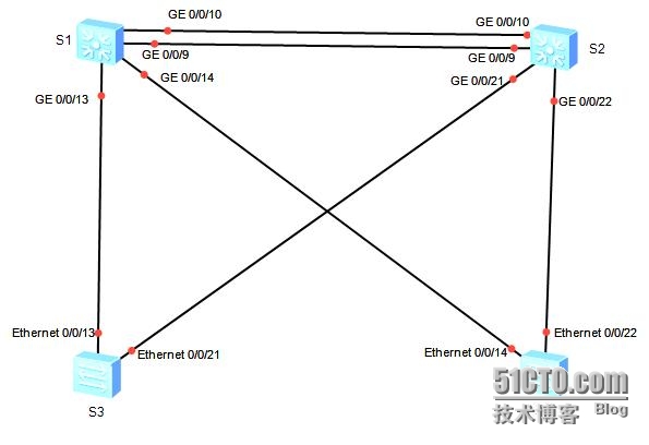
拓扑图
场景
你是公司的网络管理员。公司的网络使用了两层网络结构,核心层和接入层。采用了冗余网络,为避免存在的环路问题,决定使用STP来进行环路控制。STP有不同的模式,也可以对STP的根桥等进行控制。同样为了加快边缘网络的收敛速度,也可以使用一些特殊特性来配置STP。
学习任务
步骤一.STP配置及验证
实验之前,关闭S3的接口E0/0/1,以避免对实验的影响。
请保证设备以空配置启动。如果设备默认生成树没有开启,使用stp enable命令开启。
本次实验我们使用传统生成树。
[Huawei]sysname S1
[S1]stp mode stp
[S1]stp root secondary
[S1]
[Huawei]sysname S2
[S2]stp mode stp
[S2]stp root primary
[Huawei]sysname S3
[S3]stp mode stp
[Huawei]sysname S4
[S4]stp mode stp
使用display stpbrief 命令查看各接口简要STP状态。
[S1]display stp brief
MSTID Port Role STP State Protection
0 GigabitEthernet0/0/9 ROOT FORWARDING NONE
0 GigabitEthernet0/0/10 ALTE DISCARDING NONE
0 GigabitEthernet0/0/13 DESI FORWARDING NONE
0 GigabitEthernet0/0/14 DESI FORWARDING NONE
[S2]display stp brief
MSTID Port Role STP State Protection
0 GigabitEthernet0/0/9 DESI FORWARDING NONE
0 GigabitEthernet0/0/10 DESI FORWARDING NONE
0 GigabitEthernet0/0/21 DESI FORWARDING NONE
0 GigabitEthernet0/0/22 DESI FORWARDING NONE
[S3]display stp brief
MSTID Port Role STP State Protection
0 Ethernet0/0/13 ALTE DISCARDING NONE
0 Ethernet0/0/21 ROOT FORWARDING NONE
[S4]display stp brief
MSTID Port Role STP State Protection
0 Ethernet0/0/14 ALTE DISCARDING NONE
0 Ethernet0/0/22 ROOT FORWARDING NONE
使用display stpinterface命令查看某接口详细STP状态。
[S1]displstp interface gi0/0/10
-------[CISTGlobal Info][Mode STP]-------
CISTBridge :4096 .4c1f-cce0-2efa
ConfigTimes :Hello 2s MaxAge 20s FwDly15s MaxHop 20
ActiveTimes :Hello 2s MaxAge 20s FwDly15s MaxHop 20
CISTRoot/ERPC :0 .4c1f-ccee-152e / 1
CISTRegRoot/IRPC :4096 .4c1f-cce0-2efa / 0
CISTRootPortId :128.9
BPDU-Protection :Disabled
CISTRoot Type :Secondary root
TCor TCN received :149
TCcount per hello :0
STPConverge Mode :Normal
Timesince last TC :0 days 0h:26m:58s
Numberof TC :18
LastTC occurred :GigabitEthernet0/0/9
----[Port10(GigabitEthernet0/0/10)][DISCARDING]----
Port Protocol :Enabled
Port Role :Alternate Port
Port Priority :128
Port Cost(Dot1T ) :Config=auto / Active=1
Designated Bridge/Port :0.4c1f-ccee-152e / 128.10
Port Edged :Config=default / Active=disabled
Point-to-point :Config=auto / Active=true
Transit Limit :147 packets/hello-time
Protection Type :None
Port STP Mode :STP
Port Protocol Type :Config=auto / Active=dot1s
BPDU Encapsulation :Config=stp / Active=stp
PortTimes :Hello 2s MaxAge 20s FwDly 15sRemHop 0
TC or TCN send :32
TC or TCN received :52
BPDU Sent :87
TCN: 0, Config: 87, RST: 0, MST: 0
BPDU Received :853
TCN: 0, Config: 853, RST: 0, MST: 0
步骤二.根桥选举控制
使用display STP命令查看当前根桥信息
-------[CIST Global Info][Mode STP]-------
CIST Bridge :0 .4c1f-ccee-152e
Config Times :Hello 2s MaxAge 20s FwDly 15s MaxHop 20
Active Times :Hello 2s MaxAge 20s FwDly 15s MaxHop20
CIST Root/ERPC :0 .4c1f-ccee-152e / 0
CIST RegRoot/IRPC :0 .4c1f-ccee-152e / 0
CIST RootPortId :0.0
BPDU-Protection :Disabled
CIST Root Type :Primary root
TC or TCN received :190
TC count per hello :0
STP Converge Mode :Normal
Time since last TC :0 days 0h:30m:30s
Number of TC :17
Last TC occurred :GigabitEthernet0/0/22
………………….
实验中特别定义了S2为主根网桥,S1为备份根网桥。如上输出CISTBridge和CIST Root/ERPC字段值相同的即为根桥。
桥优先级数值越小的优先级越高,因此将S1的桥优先级改为4096,将S2的桥优先级修改为8192,S1的优先级高于S2,S1将选举为根桥。
[S1]undo stp root
[S1]stp priority 4096
[S2]undo stp root
[S2]stp priority 8192
使用display stp命令查看新的根桥信息。
[S1]displ stp
-------[CIST Global Info][Mode STP]-------
CIST Bridge :4096 .4c1f-cce0-2efa
Config Times :Hello 2s MaxAge 20s FwDly 15s MaxHop20
Active Times :Hello 2s MaxAge 20s FwDly 15s MaxHop20
CIST Root/ERPC :4096 .4c1f-cce0-2efa / 0
CISTRegRoot/IRPC :4096 .4c1f-cce0-2efa / 0
CIST RootPortId :0.0
BPDU-Protection :Disabled
TC or TCN received :179
TC count per hello :0
STP Converge Mode :Normal
Time since last TC :0 days 0h:1m:12s
Number of TC :28
Last TC occurred :GigabitEthernet0/0/9
……………………..
[S2]disp stp
-------[CIST Global Info][Mode STP]-------
CIST Bridge :8192 .4c1f-ccee-152e
Config Times :Hello 2s MaxAge 20s FwDly 15s MaxHop20
Active Times :Hello 2s MaxAge 20s FwDly 15s MaxHop20
CIST Root/ERPC :4096 .4c1f-cce0-2efa / 1
CIST RegRoot/IRPC :8192 .4c1f-ccee-152e / 0
CIST RootPortId :128.9
BPDU-Protection :Disabled
TC or TCN received :245
TC count per hello :0
STP Converge Mode :Normal
Time since last TC :0 days 0h:1m:31s
Number of TC :22
Last TC occurred :GigabitEthernet0/0/9
由以上输出可以看出,S1成为新的根桥。
关闭S1G0/0/9、0/0/10、G0/0/13、G0/0/14四个接口达到隔离S1的目的。
S1]interface gi0/0/9
[S1-GigabitEthernet0/0/9]shutdown
[S1-GigabitEthernet0/0/9]interface gi0/0/10
[S1-GigabitEthernet0/0/10]shutdown
[S1-GigabitEthernet0/0/1]interface gi0/0/13
[S1-GigabitEthernet0/0/13]shutdown
[S1-GigabitEthernet0/0/13]interfacegi0/0/14
[S1-GigabitEthernet0/0/14]shutdown
[S2]displ stp
-------[CIST Global Info][Mode STP]-------
CIST Bridge :8192 .4c1f-ccee-152e
Config Times :Hello 2s MaxAge 20s FwDly 15s MaxHop20
Active Times :Hello 2s MaxAge 20s FwDly 15s MaxHop20
CIST Root/ERPC :8192 .4c1f-ccee-152e / 0
CIST RegRoot/IRPC :8192 .4c1f-ccee-152e / 0
CIST RootPortId :0.0
BPDU-Protection :Disabled
TC or TCN received :259
TC count per hello :0
STP Converge Mode :Normal
Time since last TC :0 days 0h:2m:30s
Number of TC :25
Last TC occurred :GigabitEthernet0/0/22
………..
由以上红色突出部分可以看出,在S1失效的情况下,S2由备份根桥成为了根桥。
开启S1之前关闭的接口。
[S1]interface g0/0/9
[S1-GigabitEthernet0/0/9]undo shutdown
[S1-GigabitEthernet0/0/9]interface g0/0/10
[S1-GigabitEthernet0/0/10]undo shutdown
[S1-GigabitEthernet0/0/10]interface g0/0/13
[S1-GigabitEthernet0/0/13]undo shutdown
[S1-GigabitEthernet0/0/13]interface g0/0/14
[S1-GigabitEthernet0/0/14]undo shutdown
[S1]display stp
-------[CIST Global Info][Mode STP]-------
CIST Bridge :4096 .4c1f-cce0-2efa
Config Times :Hello 2s MaxAge 20s FwDly 15s MaxHop20
Active Times :Hello 2s MaxAge 20s FwDly 15s MaxHop20
CIST Root/ERPC :4096 .4c1f-cce0-2efa / 0
CIST RegRoot/IRPC :4096 .4c1f-cce0-2efa / 0
CIST RootPortId :0.0
BPDU-Protection :Disabled
TC or TCN received :183
TC count per hello :0
STP Converge Mode :Normal
Time since last TC :0 days 0h:0m:21s
Number of TC :34
Last TC occurred :GigabitEthernet0/0/13
<S2>display stp
-------[CIST Global Info][Mode STP]-------
CIST Bridge :8192 .4c1f-ccee-152e
Config Times :Hello 2s MaxAge 20s FwDly 15s MaxHop20
Active Times :Hello 2s MaxAge 20s FwDly 15s MaxHop20
CIST Root/ERPC :4096 .4c1f-cce0-2efa / 1
CIST RegRoot/IRPC :8192 .4c1f-ccee-152e / 0
CIST RootPortId :128.9
BPDU-Protection :Disabled
TC or TCN received :346
TC count per hello :0
STP Converge Mode :Normal
Time since last TC :0 days 0h:0m:39s
Number of TC :32
Last TC occurred :GigabitEthernet0/0/9
由以上输出可以看出,当S1恢复后,S1重新被选举成为根桥。
步骤三.根端口选举控制
在S2上使用displaystp brief 查看当前接口的角色信息。
<S2>display stp brief
MSTID Port Role STP State Protection
0 GigabitEthernet0/0/9 ROOT FORWARDING NONE
0 GigabitEthernet0/0/10 ALTE DISCARDING NONE
0 GigabitEthernet0/0/21 DESI FORWARDING NONE
0 GigabitEthernet0/0/22 DESI FORWARDING NONE
此时,G0/0/9为根端口,G0/0/10为替代端口。将下面通过修改S1的端口优先级的方式实现S2的端口G0/0/10成为根端口,G0/0/9成为替代端口。 修改S1接口G0/0/9和G0/0/10的端口优先级。
端口的优先级默认值为128,数值越小,因此在下面实验中我们将S1的接口G0/0/9端口优先级设置为32,G0/0/10端口优先级设置为16,。这样S1的接口G0/0/10优先级高于G0/0/9,S2的接口G0/0/10将选举为新的根端口。
[S1]interface g0/0/9
[S1-GigabitEthernet0/0/9]stp port pri
[S1-GigabitEthernet0/0/9]stp port priority32
[S1-GigabitEthernet0/0/9]interface g0/0/10
[S1-GigabitEthernet0/0/10]stp port priority16
提示:此处是修改S1的端口优先级,而不是修改S2的端口优先级。
[S1]display stp interface gi0/0/9
…….
----[Port9(GigabitEthernet0/0/9)][FORWARDING]----
PortProtocol :Enabled
PortRole :Designated Port
Port Priority :32
PortCost(Dot1T ) :Config=auto / Active=1
Designated Bridge/Port :4096.4c1f-cce0-2efa / 32.9
PortEdged :Config=default /Active=disabled
Point-to-point :Config=auto / Active=true
Transit Limit :147 packets/hello-time
Protection Type :None
PortSTP Mode :STP
PortProtocol Type :Config=auto /Active=dot1s
BPDUEncapsulation :Config=stp / Active=stp
PortTimes :Hello 2s MaxAge 20s FwDly 15sRemHop 20
TCor TCN send :70
TCor TCN received :1
BPDUSent :545
TCN: 0, Config: 545, RST: 0, MST: 0
BPDUReceived :2
TCN: 1, Config: 1, RST: 0, MST: 0
[S1]display stp interface gi0/0/10
……..
----[Port10(GigabitEthernet0/0/10)][FORWARDING]----
PortProtocol :Enabled
PortRole :Designated Port
Port Priority :16
PortCost(Dot1T ) :Config=auto / Active=1
Designated Bridge/Port :4096.4c1f-cce0-2efa / 16.10
PortEdged :Config=default /Active=disabled
Point-to-point :Config=auto / Active=true
Transit Limit :147 packets/hello-time
Protection Type :None
PortSTP Mode :STP
PortProtocol Type :Config=auto /Active=dot1s
BPDUEncapsulation :Config=stp / Active=stp
PortTimes :Hello 2s MaxAge 20s FwDly 15sRemHop 20
TCor TCN send :52
TCor TCN received :1
BPDUSent :544
TCN: 0, Config: 544, RST: 0, MST: 0
BPDUReceived :2
TCN: 1, Config: 1, RST: 0, MST: 0
在S2上使用display stp brief 查看当前接口的角色信息。
<S2>display stp brief
MSTID Port Role STP State Protection
0 GigabitEthernet0/0/9 ALTE DISCARDING NONE
0 GigabitEthernet0/0/10 ROOT FORWARDING NONE
0 GigabitEthernet0/0/21 DESI FORWARDING NONE
0 GigabitEthernet0/0/22 DESI FORWARDING NONE
有上输出可以看出,S2的接口G0/0/10被选举成为了新的根端口。G0/0/9成为了替代端口。
关闭S2上的根端口G0/0/10,观察替代端口选举为新的根端口的情况。
[S2]interface g0/0/10
[S2-GigabitEthernet0/0/10]shutdown
[S2]display stp brief
MSTID Port Role STP State Protection
0 GigabitEthernet0/0/9 ROOT FORWARDING NONE
0 GigabitEthernet0/0/21 DESI FORWARDING NONE
0 GigabitEthernet0/0/22 DESI FORWARDING NONE
此时G0/0/9被选举成为了新的根端口。
步骤四.边缘端口设置
将连接用户终端设备如计算机的端口配置成边缘端口,可以使用该端口无需经历STP计算过程快速进入转发状态。本任务中,仅作示例将S3接口E0/0/3-4配置成边缘端口,实际网络中可以根据需要配置。
[S3]interface e0/0/3
[S3-Ethernet0/0/3]stp edg
[S3-Ethernet0/0/3]stp edged-port en
[S3-Ethernet0/0/3]stp edged-port enable
[S3-Ethernet0/0/3]interface e0/0/4
[S3-Ethernet0/0/4]stp edged-port enable
配置完成后可以将计算机网线接入到S3的接口E0/0/3,在S3上使用dispalay stp brief命令查看端口的状态。由于E0/0/3是边缘端口就立即转变到“forwarding”状态了。
而连接其它没有配置边缘端口的E0/0/5接口则在链路UP之后要等待约30S才能达到Forwarding“状态。
附件:http://down.51cto.com/data/2364611
掌握启用和关闭STP的方法
了解不同的STP模式的差异
掌握修改网桥优先级影响根网桥选举的方法
掌握修改端口优先级影响根端口与指定端口选举的方法
掌握配置边缘的方法
拓扑图
场景
你是公司的网络管理员。公司的网络使用了两层网络结构,核心层和接入层。采用了冗余网络,为避免存在的环路问题,决定使用STP来进行环路控制。STP有不同的模式,也可以对STP的根桥等进行控制。同样为了加快边缘网络的收敛速度,也可以使用一些特殊特性来配置STP。
学习任务
步骤一.STP配置及验证
实验之前,关闭S3的接口E0/0/1,以避免对实验的影响。
请保证设备以空配置启动。如果设备默认生成树没有开启,使用stp enable命令开启。
本次实验我们使用传统生成树。
[Huawei]sysname S1
[S1]stp mode stp
[S1]stp root secondary
[S1]
[Huawei]sysname S2
[S2]stp mode stp
[S2]stp root primary
[Huawei]sysname S3
[S3]stp mode stp
[Huawei]sysname S4
[S4]stp mode stp
使用display stpbrief 命令查看各接口简要STP状态。
[S1]display stp brief
MSTID Port Role STP State Protection
0 GigabitEthernet0/0/9 ROOT FORWARDING NONE
0 GigabitEthernet0/0/10 ALTE DISCARDING NONE
0 GigabitEthernet0/0/13 DESI FORWARDING NONE
0 GigabitEthernet0/0/14 DESI FORWARDING NONE
[S2]display stp brief
MSTID Port Role STP State Protection
0 GigabitEthernet0/0/9 DESI FORWARDING NONE
0 GigabitEthernet0/0/10 DESI FORWARDING NONE
0 GigabitEthernet0/0/21 DESI FORWARDING NONE
0 GigabitEthernet0/0/22 DESI FORWARDING NONE
[S3]display stp brief
MSTID Port Role STP State Protection
0 Ethernet0/0/13 ALTE DISCARDING NONE
0 Ethernet0/0/21 ROOT FORWARDING NONE
[S4]display stp brief
MSTID Port Role STP State Protection
0 Ethernet0/0/14 ALTE DISCARDING NONE
0 Ethernet0/0/22 ROOT FORWARDING NONE
使用display stpinterface命令查看某接口详细STP状态。
[S1]displstp interface gi0/0/10
-------[CISTGlobal Info][Mode STP]-------
CISTBridge :4096 .4c1f-cce0-2efa
ConfigTimes :Hello 2s MaxAge 20s FwDly15s MaxHop 20
ActiveTimes :Hello 2s MaxAge 20s FwDly15s MaxHop 20
CISTRoot/ERPC :0 .4c1f-ccee-152e / 1
CISTRegRoot/IRPC :4096 .4c1f-cce0-2efa / 0
CISTRootPortId :128.9
BPDU-Protection :Disabled
CISTRoot Type :Secondary root
TCor TCN received :149
TCcount per hello :0
STPConverge Mode :Normal
Timesince last TC :0 days 0h:26m:58s
Numberof TC :18
LastTC occurred :GigabitEthernet0/0/9
----[Port10(GigabitEthernet0/0/10)][DISCARDING]----
Port Protocol :Enabled
Port Role :Alternate Port
Port Priority :128
Port Cost(Dot1T ) :Config=auto / Active=1
Designated Bridge/Port :0.4c1f-ccee-152e / 128.10
Port Edged :Config=default / Active=disabled
Point-to-point :Config=auto / Active=true
Transit Limit :147 packets/hello-time
Protection Type :None
Port STP Mode :STP
Port Protocol Type :Config=auto / Active=dot1s
BPDU Encapsulation :Config=stp / Active=stp
PortTimes :Hello 2s MaxAge 20s FwDly 15sRemHop 0
TC or TCN send :32
TC or TCN received :52
BPDU Sent :87
TCN: 0, Config: 87, RST: 0, MST: 0
BPDU Received :853
TCN: 0, Config: 853, RST: 0, MST: 0
步骤二.根桥选举控制
使用display STP命令查看当前根桥信息
-------[CIST Global Info][Mode STP]-------
CIST Bridge :0 .4c1f-ccee-152e
Config Times :Hello 2s MaxAge 20s FwDly 15s MaxHop 20
Active Times :Hello 2s MaxAge 20s FwDly 15s MaxHop20
CIST Root/ERPC :0 .4c1f-ccee-152e / 0
CIST RegRoot/IRPC :0 .4c1f-ccee-152e / 0
CIST RootPortId :0.0
BPDU-Protection :Disabled
CIST Root Type :Primary root
TC or TCN received :190
TC count per hello :0
STP Converge Mode :Normal
Time since last TC :0 days 0h:30m:30s
Number of TC :17
Last TC occurred :GigabitEthernet0/0/22
………………….
实验中特别定义了S2为主根网桥,S1为备份根网桥。如上输出CISTBridge和CIST Root/ERPC字段值相同的即为根桥。
桥优先级数值越小的优先级越高,因此将S1的桥优先级改为4096,将S2的桥优先级修改为8192,S1的优先级高于S2,S1将选举为根桥。
[S1]undo stp root
[S1]stp priority 4096
[S2]undo stp root
[S2]stp priority 8192
使用display stp命令查看新的根桥信息。
[S1]displ stp
-------[CIST Global Info][Mode STP]-------
CIST Bridge :4096 .4c1f-cce0-2efa
Config Times :Hello 2s MaxAge 20s FwDly 15s MaxHop20
Active Times :Hello 2s MaxAge 20s FwDly 15s MaxHop20
CIST Root/ERPC :4096 .4c1f-cce0-2efa / 0
CISTRegRoot/IRPC :4096 .4c1f-cce0-2efa / 0
CIST RootPortId :0.0
BPDU-Protection :Disabled
TC or TCN received :179
TC count per hello :0
STP Converge Mode :Normal
Time since last TC :0 days 0h:1m:12s
Number of TC :28
Last TC occurred :GigabitEthernet0/0/9
……………………..
[S2]disp stp
-------[CIST Global Info][Mode STP]-------
CIST Bridge :8192 .4c1f-ccee-152e
Config Times :Hello 2s MaxAge 20s FwDly 15s MaxHop20
Active Times :Hello 2s MaxAge 20s FwDly 15s MaxHop20
CIST Root/ERPC :4096 .4c1f-cce0-2efa / 1
CIST RegRoot/IRPC :8192 .4c1f-ccee-152e / 0
CIST RootPortId :128.9
BPDU-Protection :Disabled
TC or TCN received :245
TC count per hello :0
STP Converge Mode :Normal
Time since last TC :0 days 0h:1m:31s
Number of TC :22
Last TC occurred :GigabitEthernet0/0/9
由以上输出可以看出,S1成为新的根桥。
关闭S1G0/0/9、0/0/10、G0/0/13、G0/0/14四个接口达到隔离S1的目的。
S1]interface gi0/0/9
[S1-GigabitEthernet0/0/9]shutdown
[S1-GigabitEthernet0/0/9]interface gi0/0/10
[S1-GigabitEthernet0/0/10]shutdown
[S1-GigabitEthernet0/0/1]interface gi0/0/13
[S1-GigabitEthernet0/0/13]shutdown
[S1-GigabitEthernet0/0/13]interfacegi0/0/14
[S1-GigabitEthernet0/0/14]shutdown
[S2]displ stp
-------[CIST Global Info][Mode STP]-------
CIST Bridge :8192 .4c1f-ccee-152e
Config Times :Hello 2s MaxAge 20s FwDly 15s MaxHop20
Active Times :Hello 2s MaxAge 20s FwDly 15s MaxHop20
CIST Root/ERPC :8192 .4c1f-ccee-152e / 0
CIST RegRoot/IRPC :8192 .4c1f-ccee-152e / 0
CIST RootPortId :0.0
BPDU-Protection :Disabled
TC or TCN received :259
TC count per hello :0
STP Converge Mode :Normal
Time since last TC :0 days 0h:2m:30s
Number of TC :25
Last TC occurred :GigabitEthernet0/0/22
………..
由以上红色突出部分可以看出,在S1失效的情况下,S2由备份根桥成为了根桥。
开启S1之前关闭的接口。
[S1]interface g0/0/9
[S1-GigabitEthernet0/0/9]undo shutdown
[S1-GigabitEthernet0/0/9]interface g0/0/10
[S1-GigabitEthernet0/0/10]undo shutdown
[S1-GigabitEthernet0/0/10]interface g0/0/13
[S1-GigabitEthernet0/0/13]undo shutdown
[S1-GigabitEthernet0/0/13]interface g0/0/14
[S1-GigabitEthernet0/0/14]undo shutdown
[S1]display stp
-------[CIST Global Info][Mode STP]-------
CIST Bridge :4096 .4c1f-cce0-2efa
Config Times :Hello 2s MaxAge 20s FwDly 15s MaxHop20
Active Times :Hello 2s MaxAge 20s FwDly 15s MaxHop20
CIST Root/ERPC :4096 .4c1f-cce0-2efa / 0
CIST RegRoot/IRPC :4096 .4c1f-cce0-2efa / 0
CIST RootPortId :0.0
BPDU-Protection :Disabled
TC or TCN received :183
TC count per hello :0
STP Converge Mode :Normal
Time since last TC :0 days 0h:0m:21s
Number of TC :34
Last TC occurred :GigabitEthernet0/0/13
<S2>display stp
-------[CIST Global Info][Mode STP]-------
CIST Bridge :8192 .4c1f-ccee-152e
Config Times :Hello 2s MaxAge 20s FwDly 15s MaxHop20
Active Times :Hello 2s MaxAge 20s FwDly 15s MaxHop20
CIST Root/ERPC :4096 .4c1f-cce0-2efa / 1
CIST RegRoot/IRPC :8192 .4c1f-ccee-152e / 0
CIST RootPortId :128.9
BPDU-Protection :Disabled
TC or TCN received :346
TC count per hello :0
STP Converge Mode :Normal
Time since last TC :0 days 0h:0m:39s
Number of TC :32
Last TC occurred :GigabitEthernet0/0/9
由以上输出可以看出,当S1恢复后,S1重新被选举成为根桥。
步骤三.根端口选举控制
在S2上使用displaystp brief 查看当前接口的角色信息。
<S2>display stp brief
MSTID Port Role STP State Protection
0 GigabitEthernet0/0/9 ROOT FORWARDING NONE
0 GigabitEthernet0/0/10 ALTE DISCARDING NONE
0 GigabitEthernet0/0/21 DESI FORWARDING NONE
0 GigabitEthernet0/0/22 DESI FORWARDING NONE
此时,G0/0/9为根端口,G0/0/10为替代端口。将下面通过修改S1的端口优先级的方式实现S2的端口G0/0/10成为根端口,G0/0/9成为替代端口。 修改S1接口G0/0/9和G0/0/10的端口优先级。
端口的优先级默认值为128,数值越小,因此在下面实验中我们将S1的接口G0/0/9端口优先级设置为32,G0/0/10端口优先级设置为16,。这样S1的接口G0/0/10优先级高于G0/0/9,S2的接口G0/0/10将选举为新的根端口。
[S1]interface g0/0/9
[S1-GigabitEthernet0/0/9]stp port pri
[S1-GigabitEthernet0/0/9]stp port priority32
[S1-GigabitEthernet0/0/9]interface g0/0/10
[S1-GigabitEthernet0/0/10]stp port priority16
提示:此处是修改S1的端口优先级,而不是修改S2的端口优先级。
[S1]display stp interface gi0/0/9
…….
----[Port9(GigabitEthernet0/0/9)][FORWARDING]----
PortProtocol :Enabled
PortRole :Designated Port
Port Priority :32
PortCost(Dot1T ) :Config=auto / Active=1
Designated Bridge/Port :4096.4c1f-cce0-2efa / 32.9
PortEdged :Config=default /Active=disabled
Point-to-point :Config=auto / Active=true
Transit Limit :147 packets/hello-time
Protection Type :None
PortSTP Mode :STP
PortProtocol Type :Config=auto /Active=dot1s
BPDUEncapsulation :Config=stp / Active=stp
PortTimes :Hello 2s MaxAge 20s FwDly 15sRemHop 20
TCor TCN send :70
TCor TCN received :1
BPDUSent :545
TCN: 0, Config: 545, RST: 0, MST: 0
BPDUReceived :2
TCN: 1, Config: 1, RST: 0, MST: 0
[S1]display stp interface gi0/0/10
……..
----[Port10(GigabitEthernet0/0/10)][FORWARDING]----
PortProtocol :Enabled
PortRole :Designated Port
Port Priority :16
PortCost(Dot1T ) :Config=auto / Active=1
Designated Bridge/Port :4096.4c1f-cce0-2efa / 16.10
PortEdged :Config=default /Active=disabled
Point-to-point :Config=auto / Active=true
Transit Limit :147 packets/hello-time
Protection Type :None
PortSTP Mode :STP
PortProtocol Type :Config=auto /Active=dot1s
BPDUEncapsulation :Config=stp / Active=stp
PortTimes :Hello 2s MaxAge 20s FwDly 15sRemHop 20
TCor TCN send :52
TCor TCN received :1
BPDUSent :544
TCN: 0, Config: 544, RST: 0, MST: 0
BPDUReceived :2
TCN: 1, Config: 1, RST: 0, MST: 0
在S2上使用display stp brief 查看当前接口的角色信息。
<S2>display stp brief
MSTID Port Role STP State Protection
0 GigabitEthernet0/0/9 ALTE DISCARDING NONE
0 GigabitEthernet0/0/10 ROOT FORWARDING NONE
0 GigabitEthernet0/0/21 DESI FORWARDING NONE
0 GigabitEthernet0/0/22 DESI FORWARDING NONE
有上输出可以看出,S2的接口G0/0/10被选举成为了新的根端口。G0/0/9成为了替代端口。
关闭S2上的根端口G0/0/10,观察替代端口选举为新的根端口的情况。
[S2]interface g0/0/10
[S2-GigabitEthernet0/0/10]shutdown
[S2]display stp brief
MSTID Port Role STP State Protection
0 GigabitEthernet0/0/9 ROOT FORWARDING NONE
0 GigabitEthernet0/0/21 DESI FORWARDING NONE
0 GigabitEthernet0/0/22 DESI FORWARDING NONE
此时G0/0/9被选举成为了新的根端口。
步骤四.边缘端口设置
将连接用户终端设备如计算机的端口配置成边缘端口,可以使用该端口无需经历STP计算过程快速进入转发状态。本任务中,仅作示例将S3接口E0/0/3-4配置成边缘端口,实际网络中可以根据需要配置。
[S3]interface e0/0/3
[S3-Ethernet0/0/3]stp edg
[S3-Ethernet0/0/3]stp edged-port en
[S3-Ethernet0/0/3]stp edged-port enable
[S3-Ethernet0/0/3]interface e0/0/4
[S3-Ethernet0/0/4]stp edged-port enable
配置完成后可以将计算机网线接入到S3的接口E0/0/3,在S3上使用dispalay stp brief命令查看端口的状态。由于E0/0/3是边缘端口就立即转变到“forwarding”状态了。
而连接其它没有配置边缘端口的E0/0/5接口则在链路UP之后要等待约30S才能达到Forwarding“状态。
附件:http://down.51cto.com/data/2364611

相关文章推荐
- 华为三层交换机STP配置
- 华为三层交换机(5328)DHCP中继应用配置实例
- 思科华为三层交换机VLAN间路由配置:
- 华为三层交换机的配置!求指教
- 华为三层交换机在vlan下配置DHCP服务
- 三层交换机配置说明(华为S5700设置三个网段互通)
- 华为三层交换机配置实例一例
- 华为USG夸三层交换机识别客户端MAC地址的配置方法
- 华为三层交换机配置方法
- 华为stp多实例配置
- 华为 三层交换机VLAN间路由配置详解
- 三层交换机配置说明(华为S5700配…
- 华为三层交换机配置方法
- 华为 交换机 配置STP
- 华为三层交换机及H3C二层交换机跨网段管理配置方法
- 华为三层交换机5700 DHCP配置
- 华为三层交换机配置DHCP配置
- 配置Multiple STP 推荐
- 三层交换机配置实例及说明